background image

www.fastech.co.kr - 23

Please refer to the Appendix when 

connects motor extension cable.
Careful connection will be required to 

protect the drive from any damages.

CAUTION

※  When connects I/O cable between controller and drive, please turn off the power 

   of both controller and drive, in order to protect the drive from any damage.

EXT_GND

EXT_24VDC

24VDC

GND

F.GND

5VDC

F.GND

Shielded

Twisted Pair

Cable

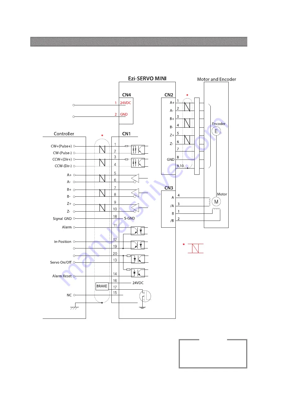
18. External Wiring Diagram

Содержание Ezi-SERVO MINI

Страница 1: ...Operating Manual www fastech motions com ...

Страница 2: ...ecifications of Motor with Brake 13 Dimensions of Motor with Brake mm 14 Specifications of Motor with Gearbox 15 Dimensions of Motor with Gearbox mm 16 Settings and Operation 16 1 Drive Status LED 16 2 Pulse Input Setting Switch SW2 6 16 3 Rotational Direction Setting Switch SW2 5 16 4 Resolution Setting Switch SW1 5 1 8 16 5 Position Controller Gain Settingn Switch SW2 1 2 4 16 6 In Position Valu...

Страница 3: ... is damaged or lost please go to the homepage www fastech motions com and downloaded the manual Our company is not responsible for a product breakdown due to user s dismantling for the product and such a breakdown is not guaranteed by the warranty Put the Safety First Before installation operation and repairing the Ezi SERVO MINI thoroughly read the manual and fully understand the contents Before ...

Страница 4: ...therwise a fire or other kinds of accidents may occur due to overheating The process of Installation Connection Operation Checking and Repairing should be done with qualified person Otherwise a fire or other kinds of accidents may occur Attention Warning Connect Cables Keep the rated range of lnput Voltage for Ezi SERVO MINI Otherwise a fire or other kinds of accidents may occur Cable connection s...

Страница 5: ... SERVO MINI The machine may get damaged or the user may get injured by motor operation All parameter values are set by default factory setting value Change this value after reading this manual throughly Otherwise the machine may get damaged or other kinds of accidents may occur Stop to supply power to the main circuit and wait for a while before checking or repairing the Ezi SERVO MINI Electricity...

Страница 6: ...rmance smoothness positional error and low servo noise conventional servo systems require the adjustment of its servo s gains as an initial crucial step Even systems that employ auto tuning require manual tuning after the system is installed especially if more that one axis are interdependent Ezi SERVO employs the best characteristics of stepper closed loop motion controls and algorithms to elimin...

Страница 7: ...stability and rapid motions within a short distance are required Traditional servo motor systems have a natural delay called settling time between the command input signals and the resultant motion because of the constant monitoring of the current position Fast Response 6 Traditional servo motor drives overshoot their position and try to correct overshooting by moving the opposite direction especi...

Страница 8: ...ping drivers use a constant current control at all speed ranges without considering load variations 1 No gain tuning Automatic gain adjustment in response to a load change 2 Maintains the stable holding position without oscillation after completion of positioning 3 Fast positioning due to the independent control by on board MCU 4 Continuous operation during rapid short stroke movement due to insta...

Страница 9: ...i SERVO MI 28S D EzM 28S D EzS PD MI 28S D Ezi SERVO MI 28SM D EzM 28SM D EzS PD MI 28S D Ezi SERVO MI 28M D EzM 28M D EzS PD MI 28M D Ezi SERVO MI 28MM D EzM 28MM D EzS PD MI 28M D Ezi SERVO MI 28L D EzM 28L D EzS PD MI 28L D Ezi SERVO MI 28LM D EzM 28LM D EzS PD MI 28L D Ezi SERVO MI 35M D EzM 35M D EzS PD MI 35M D Ezi SERVO MI 35MM D EzM 35MM D EzS PD MI 35M D Ezi SERVO MI 35L D EzM 35L D EzS P...

Страница 10: ...2M B PN15 EzM 42M B PN15 EzS PD MI 42M B Ezi SERVO MI 42M A PN25 EzM 42M A PN25 EzS PD MI 42M A 1 25 Ezi SERVO MI 42M B PN25 EzM 42M B PN25 EzS PD MI 42M B Ezi SERVO MI 42M A PN40 EzM 42M A PN40 EzS PD MI 42M A 1 40 Ezi SERVO MI 42M B PN40 EzM 42M B PN40 EzS PD MI 42M B Ezi SERVO MI 42M A PN50 EzM 42M A PN50 EzS PD MI 42M A 1 50 Ezi SERVO MI 42M B PN50 EzM 42M B PN50 EzS PD MI 42M B Ezi SERVO MI 4...

Страница 11: ...IP switch 2 Max Input Pulse Frequency 500kHz Duty 50 Protection Functions Over Current Error Over Speed Error Position Tracking Error Over Load Error Over Temperature Error Over Regenerated Voltage Error Motor Connect Error Encoder Connect Error In Position Error System Error ROM Error Position Overflow Error LED Display Power status In Position status Servo On status Alarm status In Position Sele...

Страница 12: ...Torque N m Speed rpm MODEL EzM 20 series EzM 28 series EzM 35 series EzM 42 series UNIT 20M 20L 28S 28M 28L 35M 35L 42S 42M 42L 42XL DRIVE METHOD BI POLAR NUMBER OF PHASES 2 2 2 2 2 2 2 2 2 2 2 CURRENT per PHASE A 0 5 0 5 0 95 0 95 0 95 1 5 1 5 1 2 1 2 1 2 1 2 HOLDING TORQUE N m 0 016 0 025 0 069 0 098 0 118 0 13 0 23 0 32 0 44 0 5 0 65 ROTOR INERTIA g cm2 2 5 3 3 9 0 13 18 15 20 35 54 77 114 WEIG...

Страница 13: ... add M after standard motor model number Ø16 0 05 0 20 0 5 4 16 0 1 4 M2 DP2 5 L 1 L 15 1 4 0 012 0 3 5 0 1 10 0 5 7 0 2 1 5 0 2 20 6 27 6 A 0 075 A Ø 0 075 A 0 025 Ø 15 0 5 L 1 L 13 6 1 10 0 2 2 0 2 Ø5 0 012 0 4 5 0 1 Ø22 0 05 0 28 0 5 4 23 0 15 4 M2 5 DP2 5 31 28 0 075 A Ø 0 075 A A 0 025 15 0 5 L 1 L 13 6 1 10 0 2 2 0 2 Ø5 0 012 0 4 5 0 1 Ø22 0 05 0 28 0 5 4 23 0 15 28 3 4 M2 5 DP2 5 47 2 A 0 0...

Страница 14: ... M after standard motor model number 11 Notes on Installation 1 Ezi SERVO MINI is designed for indoor use only 2 The ambient temperature of the room should be 0 50 3 If the temperature of the product case is higher than 50 radiate heat of the outside to cool down 4 Do not install Ezi SERVO MINI under direct rays near magnetic or radioactive objects 5 If you set more than 2 drives you must set over...

Страница 15: ...42S BK Non exci tation run Type 24VDC 10 0 2 5 0 2 510 22 26 33 46 Must be Lower than Unit s Weight Ezi SERVO MI 42M BK EzM 42M BK 570 Ezi SERVO MI 42L BK EzM 42L BK 640 Ezi SERVO MI 42XL BK EzM 42XL BK 770 The code of encoder resolution will be marked in Electronic Brake cannot be used for braking Position hold purpose only when power OFF The weight means Motor Unit Weight including Motor and Ele...

Страница 16: ...O MI 42M PN15 4 14 5 7 15 0 0024 6 12 0 200 1 06 410 540 Ezi SERVO MI 42M PN25 6 90 25 0 00144 9 18 0 120 490 640 Ezi SERVO MI 42M PN40 9 00 40 0 0009 9 18 0 75 570 640 Ezi SERVO MI 42M PN50 9 00 50 0 00072 9 18 0 60 620 640 Ezi SERVO MI 42L PN3 0 93 77x10 7 3 5 3 0 012 6 12 0 1000 1 02 240 270 Ezi SERVO MI 42L PN5 1 55 5 0 0072 9 18 0 600 290 330 Ezi SERVO MI 42L PN8 2 48 8 0 0045 9 18 0 375 340 ...

Страница 17: ...50 34 Ezi SERVO MI 42M PN EzM 42M PN 15 25 40 50 40 Ezi SERVO MI 42L PN EzM 42L PN 15 25 40 50 48 Ezi SERVO MI 42XL PN EzM 42XL PN 15 25 40 50 60 4 ø3 4 THRU P C D 50 2 54 42 M4 DP10 5 26 R 0 4 19 5 16 2 88 5 L 112 5 1 L 24 1 62 5 4 42 5 5 L 1 ø35 0 025 g6 0 009 ø13 0 003 j6 0 008 0 025 0 1 A 0 5 A A 4 ø3 4 THRU P C D 50 54 42 42 26 R 0 4 19 5 16 2 105 L 129 1 L 24 1 79 4 5 5 L 1 ø35 0 025 g6 0 00...

Страница 18: ...as Pulse input signal ON 1 Pulse mode OFF 2 Pulse mode Default 2 Pulse mode CW Pulse Pin CCW Dir Pin Rotational Direction CW CW CCW CCW 2 Pulse Mode 1 Pulse Mode Protection functions and LED flash times Times Protection Conditions 1 Over Current Error The current through power devices in inverter exceeds 4 8A 2 Over Speed Error Motor speed exceeds 3 000 rpm 3 Position Tracking Error Position error...

Страница 19: ...solution motor shall be operated by microstep between pulse 16 5 Position Controller Gain Settingn Switch SW2 1 2 4 The Position Controller Gain Switch allows for the correction of the motor position deviation after stopping caused by load and friction Depending on the motor load the user may have to select a different gain position to stabilize and to correct positional error quickly To tune the ...

Страница 20: ...Default 0 1 19 2 20 16 7 Input Output Signal Connector CN1 16 8 Encoder Connector CN2 NO Function I O 1 A Input 2 A Input 3 B Input 4 B Input 5 Z Input 6 Z Input 7 5VDC Output 8 GND Output 9 F GND 10 F GND 1 4 16 9 Motor Connector CN3 NO Function I O 1 B Phase Output 2 B Phase Output 3 A Phase Output 4 A Phase Output 16 10 Power Connector CN4 NO Function I O 1 24VDC Input 2 GND Input 1 2 NO Functi...

Страница 21: ...F CSVI E M Normal Cable Robot Cable is for Cable Length The unit is 1m and Max 20m length Motor Extension Cable Available to extended connection between motor and Ezi SERVO MINI Item Length m Remark CMNB M F CMNB M M Normal Cable Robot Cable is for Cable Length The unit is 1m and Max 20m length Power Cable Available to connect between Power and Ezi SERVO MINI Item Length m Remark CMNB P F CMNB P M...

Страница 22: ...5557 04R 5556T MOLEX Encoder Drive Side CN2 Housing Terminal 501646 1000 501648 1000 AWG 26 28 MOLEX Encoder Side Housing Terminal SMP 09V NC SHF 001T 0 8BS JST Signal CN1 Housing Terminal 501646 2000 501648 1000 AWG 26 28 MOLEX 17 2 Connector Specifications Connector specifications for cabling to drive Above connector is the most suitable product for the drive applied Another equivalent connector...

Страница 23: ...be required to protect the drive from any damages CAUTION When connects I O cable between controller and drive please turn off the power of both controller and drive in order to protect the drive from any damage EXT_GND EXT_24VDC 24VDC GND F GND 5VDC F GND Shielded Twisted Pair Cable 18 External Wiring Diagram ...

Страница 24: ...n not displaying the voltage levels of the signal Encoder Signal Output The encoder signal is a line driver output This can be used to confirm the stop position In Position Output In Position signal is ON when positioning is completed This signal is ON when the motor position error is within the value set by the switch Alarm Output The Alarm output indicates ON when the driver is in a normal opera...

Страница 25: ...ing Connector of Motor Pin layout Pin number Pin number Pin layout 1 2 3 4 1 2 3 4 5 6 7 8 9 10 1 2 3 4 5 6 7 8 9 1 2 3 4 3 1 4 2 Appendix Extension Cable for Motor For cable extension between Motor and Drive Extension Cable for Encoder For cable extension between Encoder and Drive WIRING DIAGRAM WIRING DIAGRAM 1 9 1 2 3 4 9 1 10 2 ...

Страница 26: ...or reproduced in whole or in part described in the User s Guide If you need a user manual to the loss or damage etc please contact us or your nearest distributor User manual are subject to change without notice to improve the product or quantitative changes in specifications and user s manual Ezi SERVO is registered trademark of FASTECH Co Ltd in the national registration ⓒ Copyright 2007 FASTECH ...

Отзывы: