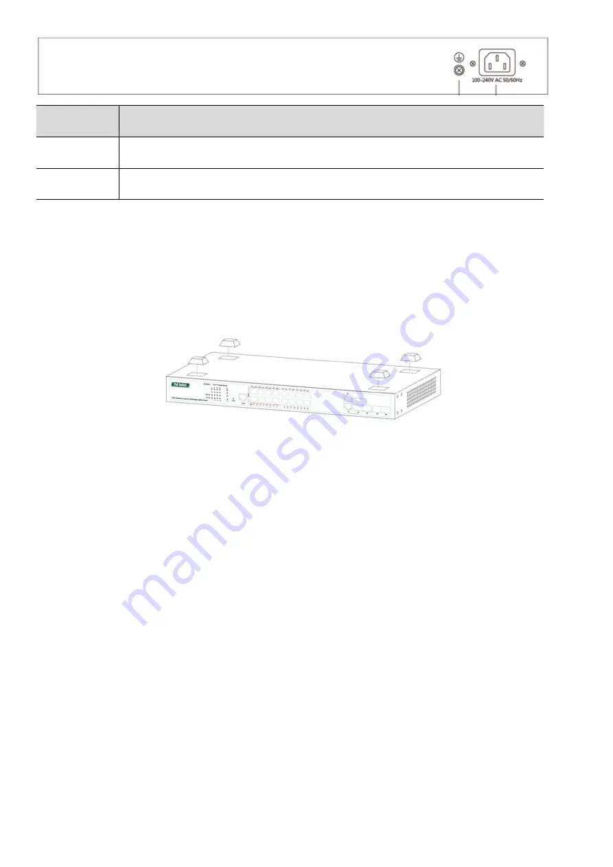
Detail
Description
Ground
ESD grounding for ESD protection. The screws and washer are included.
Power
Connect to AC power cord. 100V-240VCA 50/60Ghz.
Hardware Installation
Place the Managed switch on the flat, horizontal surface or mount it on the wall. Install the Switch on a desktop,
please attach these cushioning rubber feet provided on the bottom at each corner of the Switch in case of external
vibration. Allow adequate space for ventilation between the device and the objects around it.
Connecting the Switch
The switch accepts AC voltage range from 100V-240VAC 50/60Ghz. The input voltage is higher or lower than the
range may damage the switch.
NOTE: Be sure you never connect two uplink ports to the same core switch or router which will create ring network
and block all the network accessing.
1. First, connect AC power cord to the power port at the rear of your switch.
2. Next, connect the other end to the power outlet. In a short while, power indicator will be turned on.
3. Then connect the Ethernet cable to one of the uplink ports, and connect the other end of this Ethernet cable to a
core switch or router. Now you have attached this switch to your main network.
4. Next, you can choose one of the RJ45 ports and use Ethernet cable to connect it to your IP devices such as Edge
switch, IP camera, VoIP or access point etc.
Using the SFP Port (Optional)
The managed switch has SFP uplink ports which provides long distance transmission with low latency over fiber optic
cable. You will need SFP module (not included) to connect managed Switch to another fiber device. To use SFP port
1. First Remove the protective plug covering on the SFP port.
2. Next Insert the SFP module into one of the SFP ports.


