background image

  26

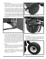
Move latches switch (G) to field position and hold to

fully engage wing latches (H).

Move flip wing switch (I) to field position and hold to

to unfold flip wings.

The  toolbar  should  be  completely  unfolded  with

wing tips angled up in the kicked position. To set

desired height of wing kick, hold down in rest toggle

switch (J) until wings are slightly below desired kick

height. Install depth stops on cylinder rod of wing

kick/down pressure cylinders on both sides of the

toolbar according to amount of wing kick preferred.

MAIN WINGS

DOWN IN REST

FLIP WINGS

LATCHES

DANGER: Never unfold toolbar under overhead wires

WARNING: Always lock toolbar before transport

G

FIELD

TRANSPORT

MAIN WINGS

DOWN IN REST

FLIP WINGS

LATCHES

DANGER: Never unfold toolbar under overhead wires

WARNING: Always lock toolbar before transport

I

FIELD

TRANSPORT

J

Tractor remote lever (purple labeled hose) may now

be disengaged and returned to neutral until a wing

folding function is required.

Check  amount  of  down  pressure  applied  to  main

wings  by  engaging  remote  #1  continuously  and

lowering  coulters  into  the  ground  while  remaining

stationary with unit. Hydraulic down pressure gauge

should  read  between  700  and  1500  psi.  Down

pressure may be adjusted by turning socket head

screw on down pressure valve located on toolbar

near wing fold manifold.

Use  only  as  much  down  pressure  as  needed  to

get  coulters  to  proper  depth.  Excess  pressure

could cause damage to toolbar. Turn socket head

screw  clockwise  to  increase  pressure  and  turn

counter clockwise to decrease down pressure. To

change pressure, loosen jam nut, turn adjustment

stem a 1/4 turn at a time. Do not exceed 1500 PSI.

Reverse the tractor remote #1 to fully raise toolbar

and  kick  wings  up. Toolbar  is  now  ready  for  field

application.

Outer Wing Valve - 60 Ft Machines:

14.

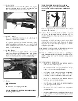
Chemical  lines  to  outer  wings  have  a  valve  to  shut

off flow to nozzles on Flip wing. Turn valves (K) off to

get a 40 ft. application width. Open valves when 40 ft.

requirements are finished. Right wing valve illustrated.

Содержание 8200

Страница 1: ...8200 Liquid Fertilizer Applicator OPERATION MANUAL FAST GLOBAL SOLUTIONS 4130 Commerce Boulevard Windom MN 56101...

Страница 2: ...ess written permission from FAST Ag Solutions Parts information in this manual represents components installed when product was manufactured based upon the best available information Modifications mad...

Страница 3: ...y addressed as follows FAST GLOBAL SOLUTIONS 4130 Commerce Boulevard Windom MN 56101 This warranty shall expire one 1 year after the date of delivery of the new machinery If these conditions are fulfi...

Страница 4: ...___________________________________ Delivery Date____________________________________________________________________________________ DEALER INSPECTION REPORT SAFETY ____All Fasteners Tight ____ Safet...

Страница 5: ...orm 13 2 11 Safety Sign Locations 14 3 Operation 17 3 1 New Operator Or Owner 17 3 2 Machine Components 17 3 3 Break In 19 3 4 Pre Operation Checklist 19 3 5 Equipment Matching 20 3 6 Controls 20 3 7...

Страница 6: ...6 5 Troubleshooting 35 6 Specifications 36 6 1 Mechanical 36 6 2 Hydraulic Fitting Torque 36...

Страница 7: ...hat you and anyone else who will be operating or maintaining the applicator read and understand the Safety Operation Maintenance and Trouble Shooting information contained in the Operator s Manual Thi...

Страница 8: ...and at least annually thereafter per OSHA regulation 1928 57 The most important safety device on this equipment is a SAFE operator It is the operator s responsibility to read and understand ALL Safety...

Страница 9: ...appropriate protective devices as instructed on 6 the chemical or fertilizer MSDS Lower machine to ground place all controls in neutral 7 stop engine set park brake remove ignition key and wait for al...

Страница 10: ...tay away from overhead power lines when folding or 14 extending wings and during transport Before applying pressure to hydraulic system make 15 sure all components are tight hoses and couplings are in...

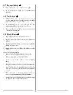
Страница 11: ...good condition 2 6 Transport Safety Read and understand ALL information in Operator s 1 Manual regarding procedures and SAFETY when operating applicator in field and or on road Check with local autho...

Страница 12: ...e safety signs that are missing or have become 2 illegible Replaced parts that displayed a safety sign should also 3 display the current sign Safety signs are available from your Distributor or the 4...

Страница 13: ...LL Safety Operatingand Maintenance information presented in this manual Do not operate or allow anyone else to operate this equipment until such information has been reviewed Annually review this info...

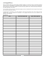
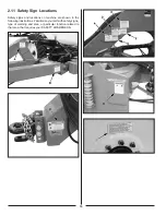
Страница 14: ...ons Safety signs and locations on machine are shown in the following illustrations Familiarize yourself with safety signs type of warning and area or particular function related to that area that requ...

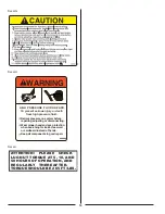
Страница 15: ...HAZARD To prevent serious personal injury or death Read and understand the owners manual before using machine Keep hands and body out of hitch area when attaching towing vehicle Always use the safety...

Страница 16: ...pressure on system before repairing adjusting or disconnecting Keep all components in good repair Wear proper hand and eye protection when searching for leaks Use wood or cardboard instead of hands 80...

Страница 17: ...efore applying pressure to the hydraulic system make sure all components are tight hoses and couplings are in good condition Review safety instructions before operating machine 3 1 New Operator Or Own...

Страница 18: ...18 A Outer Wing B Flow Control C Tank D Hitch E Center Frame F Nozzle G Liquid Line H Inner Wing I Coulter J Gauge Wheel K Rinse Tank L Pump...

Страница 19: ...rocedures and all related safety precautions outlined in this section A pre operational checklist is provided for the operator It is important for both personal safety and maintaining the good mechani...

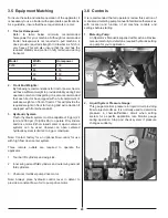
Страница 20: ...00 psi 13 800 kPa to operate lift cylinders and drive motor Either closed center or open centered systems can be used However an open centered hydraulic system is limited to 8 gpm maximum Note Contact...

Страница 21: ...ching Unhooking Tractor Make sure that all bystanders are clear of working 1 area Make sure there is enough room and clearance to safely 2 back up to machine Slowly back tractor until holes on hitch a...

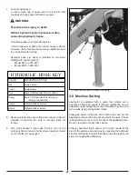
Страница 22: ...B to secure jack HYDRAULIC HOSE KEY COLOR DESCRIPTION OF USE Red Pump Pressure Yellow Pump Return Grey Main Lift Wing Kick Pressure Raise Orange Main Lift Wing Kick Return Lower Run in Constant Flow P...

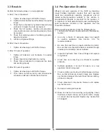
Страница 23: ...key and wait for all moving parts to stop before servicing adjusting repairing or unplugging Install and secure all guards and shields before starting or operating Keep hands feet hair and clothing a...

Страница 24: ...ace hydraulic motor control lever in detent Start into field Lower the tool bar into ground Turn on boom sections Stopping 8 Turn off boom sections Place hydraulic motor control lever in float positio...

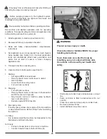
Страница 25: ...ending Tool Bar 13 Verify tool bar is fully raised Warning Prevent serious injury or death Machine coming near or contacting power lines can cause electrocution Electrocution can occur without contact...

Страница 26: ...ned to neutral until a wing folding function is required Check amount of down pressure applied to main wings by engaging remote 1 continuously and lowering coulters into the ground while remaining sta...

Страница 27: ...y incrementally turn up hydraulic flow to this circuit to make sure flow is adequate and not the problem If center section is still slow loosen jam nut and turn stem out adjust 1 4 turn at a time and...

Страница 28: ...r the job Excess liquid must be removed from the machine at the end of the season to prevent corrosion of metal parts Emptying at the end of each day is also recommended to prevent corroding over nigh...

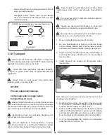
Страница 29: ...head wires WARNING Always lock toolbar before transport FIELD TRANSPORT Keep to right and yield right of way to allow faster traffic to pass Drive on the road shoulder if permitted by law Do not excee...

Страница 30: ...ease 5 cavities have been filled with grease to remove any water residue from washing Inspect all hydraulic hoses couplers and fittings Tighten 6 any loose fittings Replace any hose that is damaged or...

Страница 31: ...l moving parts to stop before servicing adjusting repairing or unplugging Follow good shop practices Keep service area clean and dry Be sure electrical outlets and tools are properly grounded Use adeq...

Страница 32: ...tilizer strainer screen using clean 3 water Grease tool bar parallel linkage 4 locations per side 8 4 total Annually Grease wheel bearings One per side 1 Remove jack from mount 2 Remove top cover and...

Страница 33: ...ht as 2 desired Install pin lock pin and tighten U bolts A 3 4 2 2 Nozzles Clear area of bystanders 1 Extend wings and raise tool bar to its fully up position 2 Place safety stands under center tool b...

Страница 34: ...structions Toxic chemicals can enter the body by breathing spray or contact with bare skin Do not take a chance with your health and safety Close sump valve A if there is liquid in tank 2 Relieve pres...

Страница 35: ...your local FAST Ag Solutions dealer or the factory Before you call please have this Operator s Manual and the serial number from your machine ready PROBLEM CAUSE SOLUTION Running out of liquid Applica...

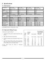
Страница 36: ...ft 70 lb ft 70 lb ft Empty Weight Of Unit lbs 1800 gal 7428 2400 gal 7528 1800 gal 8868 2400 gal 8968 1800 gal 8668 2400 gal 8768 1800 gal 9622 2400 gal 9722 Loaded Tongue Weight lbs 1800 gal 7187 24...

Страница 37: ...achine Inflate tires to shown specification NOTE Tire pressure is directly linked to LRXXX bold italic Make sure of the load rating of the tire before adding any air to the tire Tire Size Pressure 380...

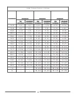
Страница 38: ...7 5 5 6 5 1 4 6 0 1 8 7 9 7 8 5 4 1 6 1 7 3 4 2 3 3 3 4 2 7 6 9 4 0 5 7 3 5 9 0 7 1 7 2 5 0 2 2 1 5 7 5 5 6 5 1 4 5 1 1 5 8 6 8 4 6 3 6 1 0 2 1 2 2 1 0 9 3 1 2 1 6 6 9 4 0 5 7 3 2 0 1 5 7 7 7 7 5 4 4...

Страница 39: ...5 5 7 0 7 5 9 2 1 M 5 9 2 0 4 7 3 0 5 5 5 5 7 0 7 5 9 0 8 0 1 1 5 0 1 0 4 1 5 9 0 3 1 0 2 1 5 6 1 4 1 M 6 4 3 6 9 5 0 8 8 8 0 2 1 0 1 1 0 5 1 0 3 1 5 7 1 5 6 1 0 2 2 0 5 1 5 0 2 0 9 1 0 6 2 6 1 M 4 7...

Страница 40: ...40 Notes...

Страница 41: ...41 Notes...

Страница 42: ...40 987 8200 Applicator Operators Manual 4 16 2019 FAST GLOBAL SOLUTIONS 4130 Commerce Boulevard Windom MN 56101 1 800 772 9279 Toll Free 1 507 427 3861 Voice 1 507 427 3030 Fax www fastsprayers com...

Отзывы: