17
16
17
18
19
20
21
Demounting
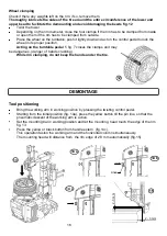
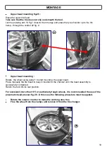
Position the pressing arm 19 fig. 7, and, through the dedicated control 22 fig. , press on the tyre edge
so that to make room enough for the extracting finger fig. 16
Activate the control 21 fig. 7 to lower the extractor hook into the working position fig. 17.
Move the presser 19 fig.7 using the special control 22 fig.8. Using the pedal 1 fig. 7 rotate the turntable
until the extractor hook is in the working position fig. 18.
Press the side of the tire using the presser 5 fig.8, controlled by the valve 22 fig.8 opposite to the
working tool, so that the bead is positioned in the hump of the rim.
Activate command 21 fig.7 to lift the extractor hook and bring the tire bead over the work tool
fig. 19 - 20, rotate the turntable clockwise using the pedal with light strokes and then continuously.
If the wheel had an inner tube, move the horizontal arm to the side and remove it from the tire.
To remove the second bead, lower the extractor hook again, using the presser 20 fig. 7 and bring the
bead on the hook fig. 21, raise the extracting hook and turn the self-centering turntable. Rotate the
horizontal arm to free the work area, then remove the tire from the rim.
Содержание RASE.TOP.2248
Страница 13: ...DECALCOMANIE 13 9 10 1 2 3 4 9 23 8 5 6 10 11 12 13 18 14 15 16 17 17 19 20 21 22 7...
Страница 38: ...LABELS 13 9 10 1 2 3 4 9 23 8 5 6 10 11 12 13 18 14 15 16 17 17 19 20 21 22 7...
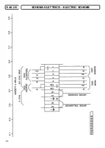
Страница 52: ...SCHEMA ELETTRICO ELECTRIC SCHEME 27 S 40 2 P...
Страница 53: ...28 SCHEMA ELETTRICO ELECTRIC SCHEME S 40 2 P...
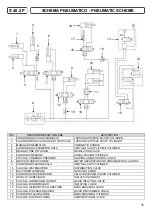
Страница 54: ...SCHEMA ELETTRICO ELECTRIC SCHEME S 40 2 E 29...
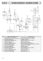
Страница 55: ...SCHEMA ELETTRICO ELECTRIC SCHEME S 40 2 E 30...


