30
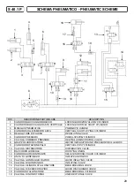
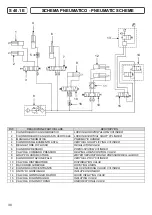
SCHEMA PNEUMATICO - PNEUMATIC SCHEME
S 40.1 E
RIF.
DESCRIZIONE PARTICOLARE
DESCRIPTION
1
CILINDRO BLOCCAGGIO BRACCIO
LOCKING HORIZONTAL ARM CYLINDER
2
CILIONDRO BLOCCAGGIO ASTA VERTICALE
LOCKING VERTICAL SHAFT CYLINDER
3
MANIGLIA PNEUMATICA
PNEUMATIC HANDLE
4
CILINDRO SOLLEVAMENTO ASTA
VERTICAL SHAFT LIFTING CYLINDER
5
REGOLATORE DI FLUSSO
REGULATION VALVE
6
CILINDRO PRESSORI
PRESS-SYSTEM CYLINDER
7
VALVOLA COMANDO PRESSORI
HELPING ARMS CONTROL VALVE
8
GRUPPO LUBRIFICATORE
WATER SEPARATOR AND PRESSURE REG.+LUBRIF.
9
CILINDRO ROTAZIONE PALO
VERTIVAL POST CYLINDER
10 VALVOLA DISTRIBUTORE
DISTRIBUTION VALVE
11 RACCORDO GIREVOLE
ROTATING UNION
12 CILINDRO AUTOCENTRANTE
SELF-CENTERING CHUCK CYLINDER
13 UNITA' DI GONFIAGGIO
INFLATE UNION BOX
14 VALVOLA GONFIAGGIO RAPIDO
QUICK INFLATING VALVE
15 VALVOLA DI GONFIAGGIO
INFLATING VALVE
16 VALVOLA DI NON RITORNO
UNIDIRECTIONAL VALVE
1
2
3
4
5
6
7
8
9
10
11
12
14
15
10
13
16
Содержание RASE.2247
Страница 13: ...DECALCOMANIE 9 10 13 1 2 3 4 13 18 14 15 9 19 8 5 6 10 11 12 16 17 7...
Страница 36: ...LABELS 13 9 10 1 2 3 4 13 18 14 15 9 19 8 5 6 10 11 12 16 17 7...
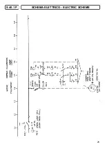
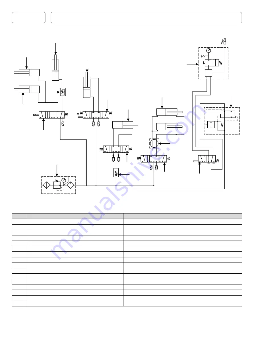
Страница 48: ...SCHEMA ELETTRICO ELECTRIC SCHEME 25 S 40 1 P...
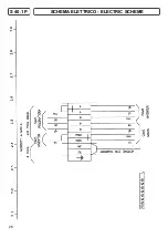
Страница 49: ...26 SCHEMA ELETTRICO ELECTRIC SCHEME S 40 1 P...
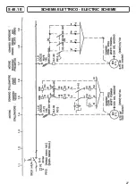
Страница 50: ...SCHEMA ELETTRICO ELECTRIC SCHEME S 40 1 E 27...
Страница 51: ...SCHEMA ELETTRICO ELECTRIC SCHEME S 40 1 E 28...


