


Operation Manual
FarSounder, Inc.
F31552 (Rev. 3.8.0)
Page 5 of 69
from that location up to the Power Module location. This is best done while the vessel is in dry-dock, but
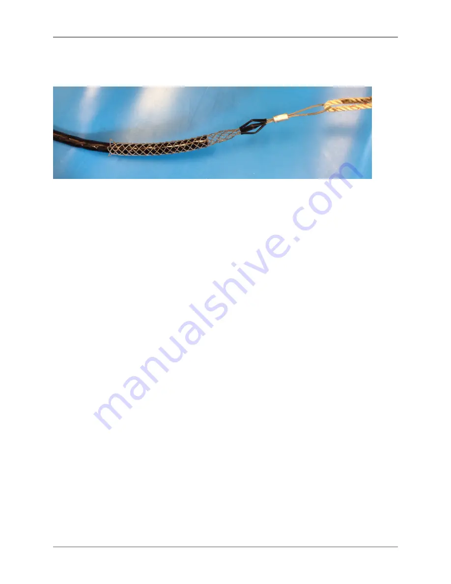
FarSounder can prepare a cable for submersion if requested. A cable puller is useful for this operation.
Figure 1. Cable with puller attached
Preparing the Dry End of the Cable
FarSounder's most current Power Module is a bulkhead mounted enclosure and the connections to the
dry end of the Transducer Module Connection Cable are made inside this enclosure. Earlier models had
2U rack mount enclosures. The latest of these models also has internal connections. Older, legacy rack
mount Power Modules have a soldered connector. See Preparing the Dry End of the Cable (Legacy Power
Modules) for preparation details for legacy Power Modules with soldered connectors.
• Remove about 7.5" (19 cm) of the urethane jacket and braided shield from the end of the cable. This
will expose the bundled wires. Be sure not to damage the internal conductors.
• Remove the Power Module cover to access the inside. The current model has four screws at the corners
of the access panel. Disconnect the ribbon cable attached to the Power Module LEDs on the cover
panel. The later rack mount enclosure has a removable access panel on the top of the chassis towards
the rear of the unit.
• Terminate the cable's cat-5e with a standard RJ-45 as described in the following subsections.
• Terminate the cable's coax cable with the supplied BNC connector as described in the following
subsections.
• Prepare the remaining conductors for connecting to a terminal strip by stripping the end of the wires.
• Feed the Transducer Module Cable through the larger of the two cable glands. Inside the Power Module
the cable connects to the Power Module electronics via standard RJ-45, BNC, and terminal block
connections described below.
• Mate the connections as described in the following subsections.
• The ethernet cable to the bridge can also be installed at this time. This connection should be tested
for 1 Gbps connection between the Power Module to the bridge computer. Industrial Cat-6 or better
is recommended.