background image

Operation Manual

FarSounder, Inc.

F31552 (Rev. 3.8.0)

Page 30 of 69

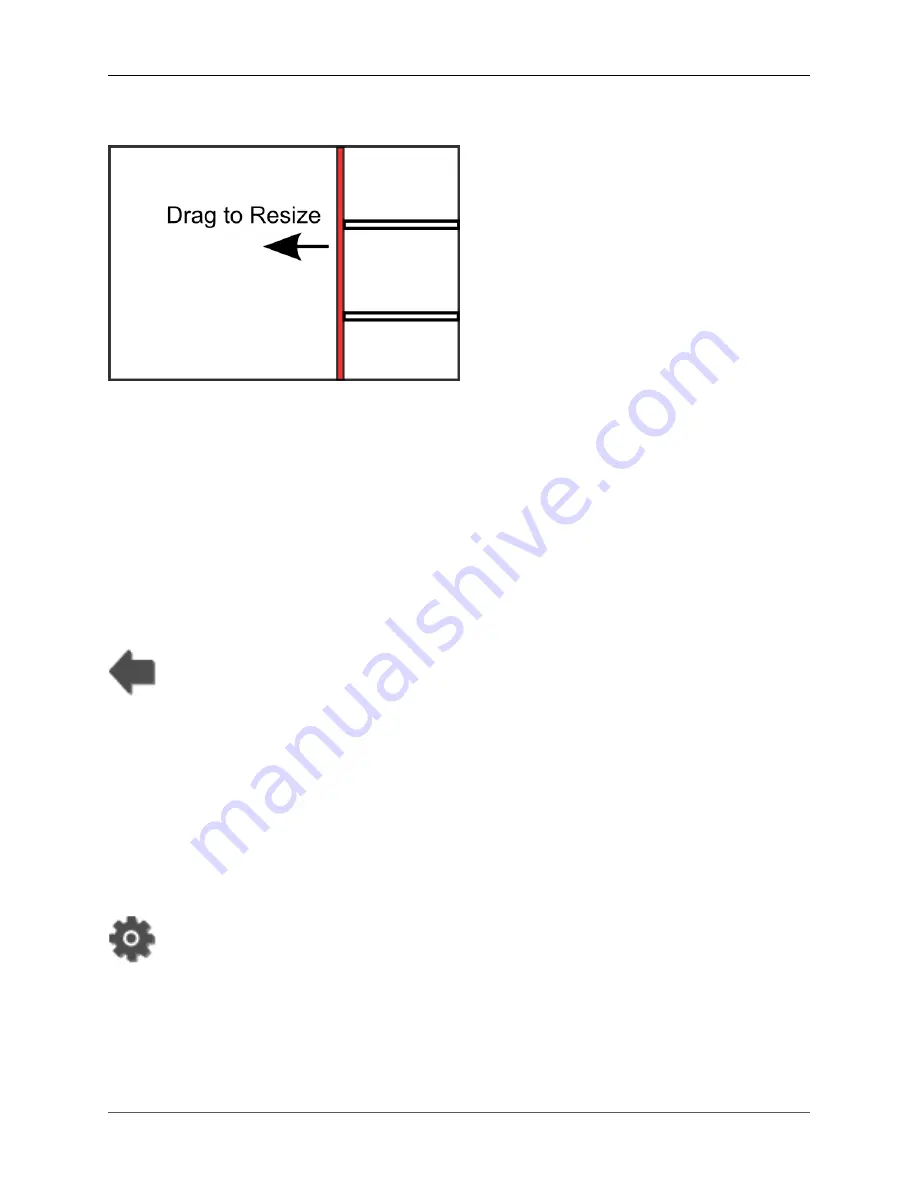
Dragging the Sidebar

Figure 31. Left Click and Drag to resize the sidebar workspace

Between the two workspaces there is a vertical bar called the sidebar resize splitter. The user can drag
the splitter with the mouse to resize the sidebar. To hide the sidebar (and all the windows it contains), drag
the resize splitter to the right side of the screen. To quickly toggle between showing and hiding the sidebar
workspace, double click on the resize splitter.

Resizing Sidebar Windows

The sidebar window views always take up the full width of the sidebar. As a result, the only way to resize
the window is the sizer bar along the bottom border. To resize a sidebar window, click on the resizer bar
and drag with the mouse while holding down the left mouse button.

Swapping Sidebar and Main Workspace Displays

The Swap-with-Main-Workspace Button moves a display from the sidebar workspace and places it in the
main workspace. It is located on the dropdown toolbar. The view previously displayed in the main workspace
is moved to the location sidebar where the new display in the main workspace was previously located.

3.3. Using The Application Buttons

At the very top left of SonaSoft™, are several buttons. These buttons are used to access menus and options
for advanced controls and features.

Configuration Manager

The configuration manager button is shaped like a gear. Clicking this button displays the system menu.
This menu provides access to:

• Configuration options for various components

• The System Status display

Содержание 1000

Страница 1: ... farsounder com www farsounder com Copyright 2002 2017 FarSounder Inc FarSounder is committed to providing the best quality and performance possible with our products As part of this policy all information herein is subject to change as new and improved versions of our software and hardware are released FarSounder the FarSounder logo Power Module Transducer Module and SonaSoft are trademarks of Fa...

Страница 2: ...w 35 4 2 Connecting NMEA Devices 35 4 3 System Settings Options 37 4 4 Chart Setup 38 5 The 3D Sonar Display 39 5 1 Overview 39 5 2 3D Volumetric Standard View 39 5 3 Profile View 40 5 4 Forward Looking Alarm Use 41 5 5 Additional Configuration Manager Options 42 5 6 Menu Bar Controls 43 5 7 Mouse Controls 44 5 8 3D Sonar Processing Options 45 6 Chart Display 47 6 1 Overview 47 6 2 Chart Overlay E...

Страница 3: ...d Wake Interference 62 4 Sea State Limitations 63 5 Vessel Speed Limitations 64 D Maintenance 65 1 Overview 65 2 Every 3 Months 65 3 Every 6 Months 65 E Troubleshooting 66 1 Overview 66 2 Power Module LED Descriptions 66 3 Power Module LED Diagnostics 66 4 C MAP Chart Display Missing Data Around Border 69 ...

Страница 4: ...e Transducer Module Connection Cable This cable is a custom designed to connect a FarSounder Transducer Module to a FarSounder Power Module The wet end connector can be connected dry or underwater The wet end connector should not be left unconnected while wet or underwater for extended periods of time A wet end connector cap is shipped with the cable for use during extended periods of unconnected ...

Страница 5: ... not to damage the internal conductors Remove the Power Module cover to access the inside The current model has four screws at the corners of the access panel Disconnect the ribbon cable attached to the Power Module LEDs on the cover panel The later rack mount enclosure has a removable access panel on the top of the chassis towards the rear of the unit Terminate the cable s cat 5e with a standard ...

Страница 6: ...ad mount Power Module Figure 3 Example termination inside rack mount Power Module Terminating the Cat 5e Cable Standard T568B wiring should be used for the Cat 5e cable coming out of the Transducer Module Connection Cable bundle It is recommended that the Ethernet cable used to connect the Power Module to ...

Страница 7: ...mp terminating the coax cable Recommended Tools Listed below are the tools that FarSounder uses though many equivalent tools exist Description Use Manufacturer MFR Part Number Rotary Cable Stripper Removing outer jacket of sonar cable Tyco 606700 1 Coax Cable Stripper Prepping Transmit Coax in sonar cable Paladin Tools LC CST 1255 BNC Ratchet Crimper Terminating Transmit Cable BNC Tyco 58433 2 BNC...

Страница 8: ...r fits into the correct receptacle Note that the 12 gauge conductors fit very snug into the terminal strip block Make sure that the strands of the conductor are not separated Otherwise it will be difficult to ensure a proper connection Mating the Connections Connect the BNC and RJ 45 to their respective receptacles on the Power Module s circuit board Follow the labels on the pcb to ensure that eac...

Страница 9: ... of the cable using an Amphenol 97 3106A 24 7P Circular Connector The cable is supplied with this connector unterminated so that the cable can be run through a conduit that has a smaller diameter than the connector The connector may be assembled and soldered by a qualified electrician The wiring diagram for this is shown in table 2 The dry end connector is approximately 2 inches 5 cm in diameter F...

Страница 10: ...e is a structural component only There is no need to connect it to ground Wet End Preparation The wet end of the cable is terminated with a Subconn BH16MSS connector This connector is molded onto the cable at the factory and cannot be serviced by the user This connection can be mated in a wet environment or underwater The wet end connector is approximately 2 4 inches 6 cm in diameter Warning This ...

Страница 11: ...the connector After greasing fully mate the male and female connector in order to secure optimal distribution of grease on pins and in sockets To confirm that grease has been sufficiently applied de mate and check for grease on every male pin Then re mate the connector 1 2 Transducer Module The most obvious component in your sonar system is the Transducer Module Though different models are supplie...

Страница 12: ...d Transducer Module Bow mounted Transducer Modules should be installed as far forward and as far below the water as possible on the vessel The black urethane array face should face forward with a clear view of the water ahead of the vessel Stern mounted Transducer Modules should be installed such that their field of view is not blocked by the vessel s propulsion system On the face of the unit ther...

Страница 13: ...et end connector should not be left unconnected while wet or underwater for extended periods of time A Connection Cable End Cap F24557 is supplied as standard for use during transport installation and extended periods of unconnected wet or underwater use Installation The Transducer Module has been designed to allow for a simple one cable connection to the rest of the sonar hardware Twelve holes ar...

Страница 14: ...tion of the Transducer Module is very important There is a protrusion on the black urethane face on the front of the unit that should be at the 12 o clock position The connector on the rear of the Transducer Module should also be at the 12 o clock position As with any piece of bolted hardware the use of washers and lock washers is recommended Important Do not put caulking such as Sikaflex around t...

Страница 15: ...will not dissolve destroy or otherwise harm the urethane since it is likely that some paint will touch the edge of the urethane array face 1 3 Power Module The Power Module for FarSounder s current products is offered in a bulkhead mounted enclosure designed to be mounted in a dry location Previous products were offered with a 2U rack mount enclosure The Power Module houses the sonar system s powe...

Страница 16: ... Transducer Module Connection Cable entry into rack mount Power Module The Power Module is powered by either 110 120 or 220 240 VAC Total power consumption for the unit is approximately 100 watts continuous A power receptacle IEC 320 C14 inlet socket is used to connect AC mains power to the Power Module The recptical includes a replaceable fuse line filter and a master power switch It is recommend...

Страница 17: ...ors are generally handled by the Power Module and do not indicate a problem This LED is used for troubleshooting purposes 3 CTRL A CTRL B Indicates internal Power Module logic states These are used for debugging purposes only and have no user application The state of these LED s may change from time to time depending upon the particular mode setting of the sonar system Once the Transducer Module h...

Страница 18: ...dapter using a standard Ethernet crossover cable When connecting the sonar to multiple user interfaces the Power Module should be connected a network switch Each of the user interfaces then connect to the network switch with a standard Ethernet patch cable The switch should be 1 Gbps capable Note FarSounder recommends unmanaged switches as incorrect configuration of managed switches may cause perf...

Страница 19: ...eeded for FarSounder operation DNS not needed for FarSounder operation 1 5 SonaSoft Software SonaSoft is FarSounder s processing and display software This software communicates directly with the sonar hardware receiving all the raw data from the Transducer Module All the processing takes place inside the SonaSoft computer Base Software Installation In order to use the SonaSoft software a system sp...

Страница 20: ...ken USB dongle During the software installation process the user is offered the option to run the C MAP Setup Wizard This includes installation of the eToken drivers chart database and chart data license This process is handled by the C MAP Chart Manager utility provided by C MAP and included in the SonaSoft installer For future chart maintenance after SonaSoft installation the C MAP Chart Manager...

Страница 21: ...e most recent C MAP chart data place it in a local folder on your machine we recommend C cmap_databases Then click the Register manually button in the C MAP Chart Manger window Figure 22 Figure 22 Click the Register manually button to browse for your database folder Next browse to the folder where you saved your database and click OK If done correctly the Chart Manager should tell you that the dat...

Страница 22: ...h license number is generated for a specific database and C MAP eToken If you already have a C MAP eToken dongle the dongle ID number must be provided to C MAP If not dongles can be purchased from FarSounder or directly from C MAP Enabling S 57 63 Support An S 57 63 support license is needed to enable use of these charts within SonaSoft This license can be purchased from FarSounder After applying ...

Страница 23: ...e 25 The Add License Manually dialog box It is necessary to apply each license separately To apply a license for a particular Zone or Area select the Zone or Area from the Available Areas Datasets list Then copy the license number into the License field and click the Add License button Repeat this process for each Zone or Area that has been licensed Once the license is applied click the Close butt...

Страница 24: ...wn to choose Software Modules and click Add manually Figure 26 The Add License Manually dialog box From this window choose V3CATMGR Import S57 from the list of modules Then copy the license number into the License field and click the Add License button ENCImporter The ENCImporter imports S 57 63 charts for use within SonaSoft Figure 27 ENCImporter The steps to using S 57 charts are as follows Firs...

Страница 25: ... here will be the information about previously added permits as well as the option to add delete permits Select Add permits and add the corresponding permits for the S 63 charts Click Re authenticate Permits to verify the applied permits are valid for the imported charts If this is the first time using this application a SA Certificate must be added Click the Add SA Certificate button Figure 29 Ad...

Страница 26: ...ust as they offer radar overlay they also offer FarSounder sonar overlay In this mode SonaSoft is also configured as a network sonar server It still performs all of the sonar processing and can still be used as a stand alone sonar display Up to 4 clients can connect to the server simultaneously FarSounder s server software distributes the processed sonar data over Ethernet using FarSounder s SDK i...

Страница 27: ...em In order to run the sonar the Power Module and Transducer Module must be connected and turned on the Power Module must be on the same network as the SonaSoft host computer and SonaSoft must be running After connecting the Power Module and Transducer Module together both pieces of the hardware are powered on by turning on the power switch on the back of the Power Module There is no separate swit...

Страница 28: ...n As with any shipboard electronic systems it is highly recommended that both the user interface computer and the FarSounder Power Module be powered through a UPS 2 2 Minimum Requirements for FS 3DT FarSounder 500 and FarSounder 1000 systems CPU Intel i7 six core RAM 6 GB minimum Video Card nVidia GTX 660 with 2GB RAM Video Card Resolution 1280 x 1024 minimum NIC 1 Gb s minimum 2 ports recommended...

Страница 29: ...re much smaller The user can interact with the workspace through the following actions Managing the Sidebar Workspace Resizing the Sidebar Using the Application Buttons 3 2 Managing the Sidebar Workspace Windows in the sidebar workspace have a vertical window resizer bar along their bottom edge They also have a left arrow button which when pressed will cause the selected side bar window to swap pl...

Страница 30: ...he bottom border To resize a sidebar window click on the resizer bar and drag with the mouse while holding down the left mouse button Swapping Sidebar and Main Workspace Displays The Swap with Main Workspace Button moves a display from the sidebar workspace and places it in the main workspace It is located on the dropdown toolbar The view previously displayed in the main workspace is moved to the ...

Страница 31: ...ighting conditions The software supports Day Dusk Night and Red color themes A theme may be selected by clicking on a theme from the list Sonar Status The sonar status indicator looks like a series of sound waves moving horizontally through the water The icon informs the user about the stength of the signal and can be useful when in deep water to confirm that the sonar is operating even if no targ...

Страница 32: ...orts are configured under the Configuration Manager s NMEA Settings menu The second indicator shows that the Sonar Processor is properly configured and is in the middle of processing a ping The third indicator shows that SonaSoft is currently connected to the sonar and is awaiting data from the sensor It also indicates the sonar s current roll pitch and heading orientation relative to the earth in...

Страница 33: ... in the SonaSoft install directory and restarting SonaSoft Formatting of each entry in hotkey ini is as follows Lines prepended with a are ignored and can be used for comments action modifer keys For example the following syntax assigns the alarm toggle functionality to the key combination Control Alt a Toggle alarm on off alarm control alt a Available 3D Viewer Actions alarm toggle alarm on off v...

Страница 34: ...ch to fourth shortest range if available setprocrange5 switch to fifth shortest range if available Available Global Actions depthscaleshallow open the number pad to define the shallow end of the depth color scale depthscaledeep open the number pad to define the deep end of the depth color scale highdbscale open the number pad to define the high dB end of the signal level color scale lowdbscale ope...

Страница 35: ...stabilization True Target Motion The SonaSoft software has been designed to accept information from external sensors via standard NMEA 0183 sentences SonaSoft connects to these NMEA sensors via the host computer s COM ports SonaSoft can listen to and process the following sentences DBT DPT GGA GLL HDG HDT RMC ROT VHW and VTG In most cases the host computer s COM ports will be basic serial ports RS...

Страница 36: ...ft to listen on Available COM ports will be listed in the COM port list NMEA Message Selection At the bottom of this window there are six rows of drop down selectors where the NMEA messages to be used for Depth Heading Position Speed Over Ground Rate of Turn and Course Over Ground can be selected SonaSoft will only listen to the messages selected for each data type Each message type Depth Heading ...

Страница 37: ... yards meters kilometers miles statute miles nautical cables System Speed Units The units selected from this drop down box are used for speed measurements throughout various displays and setting controls within SonaSoft The following units are supported knots meters per second kilometers per hour miles per hour statute 3D Reference Using these radio buttons the user can set the depth reference for...

Страница 38: ...update button Figure 36 Sensor Layout Configurator 4 4 Chart Setup The SonaSoft Chart Display offers chart plotting capabilities with a real time overlay of all in water targets The display supports Professional and ENC databases from C MAP This display capability is built into the base SonaSoft product However users must purchase a C MAP eToken and chart license separately in order to load chart ...

Страница 39: ...f waves and other transient clutter If a target is tracked across multiple pings but is not detected on a subsequent ping the target is shown on the screen at the predicted location based on previous target locations and vessel movements See Appendix B Ping to Ping Target Stabilization for more information The user can select between the 3D volumetric display which allows the user to rotate the 3D...
Страница 40: ... the Profile Selector The Profile Selector denotes the angle along which a 2D depth profile ahead of the vessel is shown in the Profile View The number at the end of the profile selector denotes the bearing of the profile selector relative to the vessel s bow or the actual compass heading This option is configured in the 3D sonar view s configuration options The depth profile slice specified with ...

Страница 41: ...if the button is set to active When active the alarm button is depressed Figure 40 Alarm acknowledge button Should the alarm be triggered a warning will sound the 3D Sonar Display window will blink blue and an alarm acknowledge message box will appear in the lower left corner of the sonar viewer window Simply click the acknowledge alarm message box to acknowledge and temporarily silence the alarm ...

Страница 42: ... include reflections from bubbles in the water column and small bits of debris in the water The alarm hit number specifies the number of pings in a row that a target must be detected within the alarm volume to trigger the alarm By specifying a number higher than 1 for the hit number false alarms can be reduced For every ping with a detection within the alarm volume an internal counter is increment...

Страница 43: ...tor s indicator will read 258 When not selected the indicator will be relative to the bow In all cases the indicator in the 2D View is relative to the bow True Target Motion With True Target Motion enabled SonaSoft will use the NMEA data provided to it to update the 3D Sonar Display and the Chart Display in real time For the 3D Sonar Display this means that the seafloor and any in water targets wi...

Страница 44: ...e colored with a smoothly changing array of colors from blue to green to orange to yellow Note Targets where depth cannot be accurately determined i e beyond the sonar s water depth limit are always drawn with the signal level color map This is true even if the color map is set to depth In this case targets within the sonar s bottom mapping range and the sea floor will be displayed with their colo...

Страница 45: ...cycle This typically means that you will see the change two pings after adjusting the control since generally when you see an image that needs adjusting there is already another ping processing with those same settings internal to the software Changes will be applied to the next fresh ping Figure 43 Processor Configuration Window Processing Mode Drop Down Selector The processing mode selection dro...

Страница 46: ...re automatically determines the best detection threshold using adaptive thresholding methods Auto Squelch is the recommended operating mode for detection of in water targets Squelch Control Slider Most of the time Auto Squelch mode will perform better than manually setting the squelch level However Auto Squelch may occasionally allow too much clutter to pass through the filters In this case the us...

Страница 47: ...database from C MAP ENC databases from C MAP S 57 63 charts The Chart Display window provides various chart plotting functionalities such as showing the position of the vessel on the chart zooming in and out on the chart measuring the distance between two points on the chart and showing latitude and longitude coordinates of the cursor position Figure 44 SonaSoft Chart Display shows a sample screen...

Страница 48: ...dates received by the Digital Chart Viewer Otherwise the vessel will move across the chart with each latitude longitude position update Zoom In Clicking this button will zoom in on the scale of the chart If auto center is depressed then the boat will be at the center of the newly zoomed view If auto center is not checked then the zooming will be centered on the center of the displayed chart Zoom O...

Страница 49: ...his dialog is for experts only while troubleshooting database issues 6 5 Configuration Manager Options In order for this component to work properly NMEA compatible heading and location sensors must be connected to the SonaSoft User Interface computer These sensors include GPS loran compass etc More information on NMEA connections can be found in the chapter entitled Section 4 2 Connecting NMEA Dev...

Страница 50: ...yed as overlays on top of the chart Successive levels of presentation increase the number of elements shown Open C MAP Chart Manager Opens the C MAP chart manager to change the database in view C MAP Chart Manager Used to add or remove C MAP chart databases on the system To add a database to the system use the Search Automatically button to locate and register the database When prompted save this ...

Страница 51: ... the depth of the contour that should not be crossed to avoid grounding of the vessel This contour appears thicker than other contour lines This depth must be between the Shallow and Deep Contours Deep Contour Set the depth of the contour beyond which all depths are considered deep enough to not warrant a lot of attention This depth must be deeper than the Safety Contour Safety Depth Spot sounding...

Страница 52: ...y Mapping Overlay depicts the LHM overlay on the chart viewer Color is mapped to depth where the blue and yellow ends of the scale represent a seafloor depth of 20 meters and 2 meters respectively The contours representing the channel are clearly visible in Figure 47 Local History Mapping Overlay and in agreement with the underlying nautical chart The vessel track history see the section called Tr...

Страница 53: ...USB dongle must be installed These can be acquired from FarSounder for a nominal fee C MAP license must be installed This can be purchased through a C MAP dealer or directly from C MAP Latitude and longitude data from a GPS and heading data from a gyro compass or GPS compass must be input to SonaSoft via NMEA ...

Страница 54: ...ound in the chapter entitled Section 4 2 Connecting NMEA Devices Under the the Configuration Manager s NMEA Settings menu the user can specify the type of NMEA message to use For echo sounder depth the user can select from the following NMEA messages DBT Depth below transducer DPT Depth below the transducer with reference to keel or surface For vessel true heading the user can select from the foll...

Страница 55: ...a with FarSounder When this feature is activated a zip file will be saved to the desktop containing raw sonar data for the last few pings SonaSoft log files and all registry settings used by SonaSoft The zip file can be sent to FarSounder for evaluation The contents will allow FarSounder engineers to see exactly what was seen on the vessel It will also allow them to reprocess the raw sonar data wi...

Страница 56: ...anges Water Depth Performance is the ratio between the depth of water below the transducer and the range at which the sea bottom can be mapped As an example if a 2 water depth sonar system is operating in 50 feet of water that system can generate bottom maps only out to 100 feet Water Depth Performance is limited by various physical effects and the bottom mapping range of a sonar is primarily a fu...

Страница 57: ...range increases the angle at which the incoming sound wave hits the seafloor becomes shallower At some angle not enough energy is reflected back to the receiver to allow for sea bottom detection and mapping The FarSounder 500 and FarSounder 1000 products are specified as 8 water depth sonars This means they can map the seafloor out to a range equal to 8 times the depth below the transducer Dependi...

Страница 58: ...A 5 Reflecting off an in water target beyond bottom mapping range The ability to detect obstacles beyond a sonar s water depth limit is extremely important Vessel operators can detect the edge of rock ledges shore lines submerged coral reefs and other navigation hazards This is helpful even in charted areas For example charts often mark an area as reef or rocks but don t give the exact locations S...

Страница 59: ...es all targets the very first time they are detected waiting until their second detection to display them This significantly reduces the number of false detections caused by transient noises such as wave slaps engine noise and fleeting bubbles However it is also important to be aware that if a true target that you are expecting to see is not displayed it may be because SonaSoft is still determinin...

Страница 60: ...Generally interference is only experienced when the echo sounders on large commercial ships are close to the user s vessel and when the FarSounder is pointed towards the other ship Such interference appears on the FarSounder display as partial or whole rings of echoes all at the same range as shown in figure C 1 Usually they appear as in water targets but sometimes they can also appear as a raised...

Страница 61: ...n ensuring that their sonars will not cause any harm to any marine life The duty cycles and transmit powers are significantly lower than those of other marine acoustic systems that are commonly accepted throughout the world In fact FarSounder s products have been reviewed by scientists at the National Marine Fisheries Service and been found to have no negative impact on the marine environment 1 1 ...

Страница 62: ...bble cloud the more energy from the sonar is disrupted Bubbles are produced by a variety of things such as waves vessel wakes and turbulent current flows around stationary objects like pilings and buoys Each of these types of bubbles clouds will effect FarSounder sonars differently Waves produce bubbles by forcing pockets of air down into the water column as the waves splash and break The bigger t...

Страница 63: ...l show a short period of strong energy followed by a period of almost no energy Figure C 4 Wake interference shows an example of the sonar inside a wake The short strong energy seen is the transmit signal as it passes through the transducer before the bubbles block the signal Once the sonar passes through a wake normal operation will resume Turbulent Current Flows around stationary objects like pi...

Страница 64: ...eeds up to 20 and 25 knots respectively This rating is based upon an ideal installation where vessel induced mechanical vibration noise is not present Some vessels have significant mechanical vibration or create turbulence in front of the Transducer Module In these cases system performance may degrade at speeds less than the stated maximums Going beyond these speeds will not damage the system Howe...

Страница 65: ...eived echoes If fouling is present it can be scraped off with a simple paint scraper or the handle of a wooden paintbrush When cleaning the Transducer Module s array face it is important that the urethane is not damaged Inspect the Transducer Module s for corrosion A properly installed Transducer Module will be connected electrically to the vessel s ground and local zincs In these cases there shou...

Страница 66: ...en troubleshooting the system Here is a short description of what each LED signals Power Indicates that the Power Module has power Bank 1 Indicates that one of the two large amplifier capacitors is charged Bank 2 Indicates that the other of the two large amplifier capacitors is charged Ping Indicates that the transmit amplifier is generating an output ping CTRL A and CTRL B Indicate states of the ...

Страница 67: ...table below describes some of the LED indications Please note that the LED State column contains one circle indicator for each LED light Possible values for each indicator are as follows The light is off The light is on The light is flashing The light may be on or off ...

Страница 68: ...ion or a firmware update Flashing A B A B After powering on the Power Module while waiting for a connection to SonaSoft The Transducer Module is ready for a SonaSoft connection Flashing Simultaneously 4 times While communicating with SonaSoft Possible data collection error If this condition continues restart Power Module Flashing PING While the Power Module is powered on The system is in operation...

Страница 69: ...or the resolution of the currently connected monitor To recalibrate C MAP for the current screen resolution Run the C MAP ruler program It can be found in C Program Files x86 C Map Professional SDK Runtime Ruler exe Inside the ruler tool dialog click the Measure the Screen button A white square will appear Measure this square with a ruler enter the resulting measurements and click Ok The C MAP is ...

Отзывы: