User Manual, FD20 v2.3
Version 1.2
– December 2021
56
8.5 Preventive maintenance checks of the Safety System
The Safety System of the Robot is designed to have a lifetime of at least 30 years when correctly
maintained
. Maintenance of the Robot’s safety system should only be performed by trained professionals.
The safety system fulfills the requirements for reaching Performance Level D, Category 2.
The PLC functions as the OTE in the Category 2 test circuit.
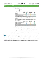
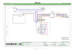
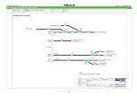
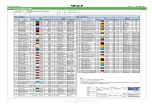
Please refer to Appendix A for electrical wiring diagrams.
Always make sure to follow the guidelines when performing maintenance work. If in doubt, please contact
your local distributor for advice before commencing the service/maintenance task.
Always remember to follow the safety instructions when performing inspections or maintenance and
service work on the Robot. Always set the Robot to manual operation and then turn off both power sources
before entering the Robot.
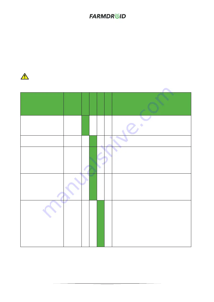
Task
Type
Daily
W
ee
kly
Mon
th
ly
Y
ea
rly
Comments
Check for general
damage on the Robot
and especially its safety
system.
Visual
check
Consult your local distributor if damages on the
safety system are detected.
Check for damage to
the visible indicators.
Visual
check
Must be replaced immediately if damaged.
Check for damage to
the audible indicator.
Audible
check
Must be replaced immediately if damaged.
The robot will automatically ask for a routine
check of the audible indicator with 2 weeks
intervals. Make sure to follow the instructions
in the HMI.
Check safety wire
tensioning.
Visual
check
Check if the safety wire tension is acceptable
and not close to the switching points on both
wire switches.
Adjust the wire tension, if necessary, by using
a 10mm spanner at each wire switch.
Safety system
Visual
check
Individually activate both emergency wire
switches and the emergency push button to
test the safety system.
Perform a separate test for each switch to
check for proper functionality.
The robot will automatically ask for a routine
check of the audible indicator with half-year
intervals. Make sure to follow the instructions
in the HMI.
Содержание FD20
Страница 1: ...FARMDROID FD20 v2 3 ORIGINAL USER MANUAL Version 1 2 Effective from December 2021 ...
Страница 7: ...User Manual FD20 v2 3 Version 1 2 December 2021 4 1 3 EU Declaration of Conformity ...
Страница 10: ...User Manual FD20 v2 3 Version 1 2 December 2021 7 ...
Страница 69: ...User Manual FD20 v2 3 Version 1 2 December 2021 B Operator Panel Schematics ...
Страница 70: ...User Manual FD20 v2 3 Version 1 2 December 2021 C Wire harness Main Tube connections ...
Страница 71: ...User Manual FD20 v2 3 Version 1 2 December 2021 D Wire harness Secondary Tube connections ...
Страница 72: ...User Manual FD20 v2 3 Version 1 2 December 2021 E Wire harness Wire Connections ...


