User Manual, FD20 v2.3
Version 1.2
– December 2021
26
Step Description
HMI Page
4
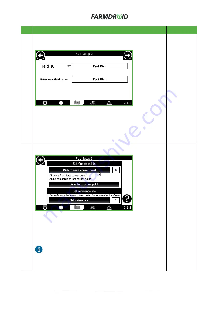
Select a field number of your own choice and enter a suitable name for the field.
When this is done, proceed to the next page by using the arrow in the top right
corner.
If the selected field is already occupied, an attention message will appear and it
will be possible to either overwrite the existing field or cancel, whereafter it is
possible to select another field entry slot.
When a field name has been entered, navigate to the next page using the arrow
in the top right corner.
3.1.1 Field
Setup 2
5
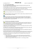
Move the Robot to the first Corner Point of the field such that the front GPS is
located at the boarder of the field. When in place,
press “Save Corner Point”.
Then move the Robot to the next corner point as instructed on the HMI - Corner
Point 1 will act as a reference point. Continue to set up the corners one by one,
by physically moving the robot to the next corner point and saving this by
pressing the “Save Corner Point” button. For each corner the number to the
right of the button will count up.
When the Robot is located at the desired reference corner point,
remember to
press “Set Reference”. This point will together with corner point 1
create the reference line. The passes will always be parallel to the reference
line.
3.1.2
Field Setup 3
Содержание FD20
Страница 1: ...FARMDROID FD20 v2 3 ORIGINAL USER MANUAL Version 1 2 Effective from December 2021 ...
Страница 7: ...User Manual FD20 v2 3 Version 1 2 December 2021 4 1 3 EU Declaration of Conformity ...
Страница 10: ...User Manual FD20 v2 3 Version 1 2 December 2021 7 ...
Страница 69: ...User Manual FD20 v2 3 Version 1 2 December 2021 B Operator Panel Schematics ...
Страница 70: ...User Manual FD20 v2 3 Version 1 2 December 2021 C Wire harness Main Tube connections ...
Страница 71: ...User Manual FD20 v2 3 Version 1 2 December 2021 D Wire harness Secondary Tube connections ...
Страница 72: ...User Manual FD20 v2 3 Version 1 2 December 2021 E Wire harness Wire Connections ...


