


reduce the vapor temperature. If due to extreme oper-
ating conditions it is necessary to further reduce the
vapor temperature, the vaporizer coil may be with-
drawn slightly toward the fan housing. If vaporizer coil
is shifted, use care not to kink gas lines or allow vapor-
izer to contact the burner vanes.
NOTE:
High vaporizer temperatures may be caused by
fuel vaporizing before reaching the vaporizer. Check
for:
A. Improper fuel hookup. Should be drawing liquid
from tank.
B. Frosted lines, fittings or valves. Frost indicates a
restriction or pressure drop in piping, causing vaporiza-
tion.
BURNER CONTROL SEQUENCE OF
OPERATION
The following text should be read in conjunction with
the Burner Control Circuit diagram in Sect. 8.
NOTE:
Power is available to a fan circuit's burner con-
trol ONLY WHEN THE FAN IS OPERATING.
1. When the fan is started and the burner switch is ON,
power is supplied to PL-021 Burner Control Board ter-
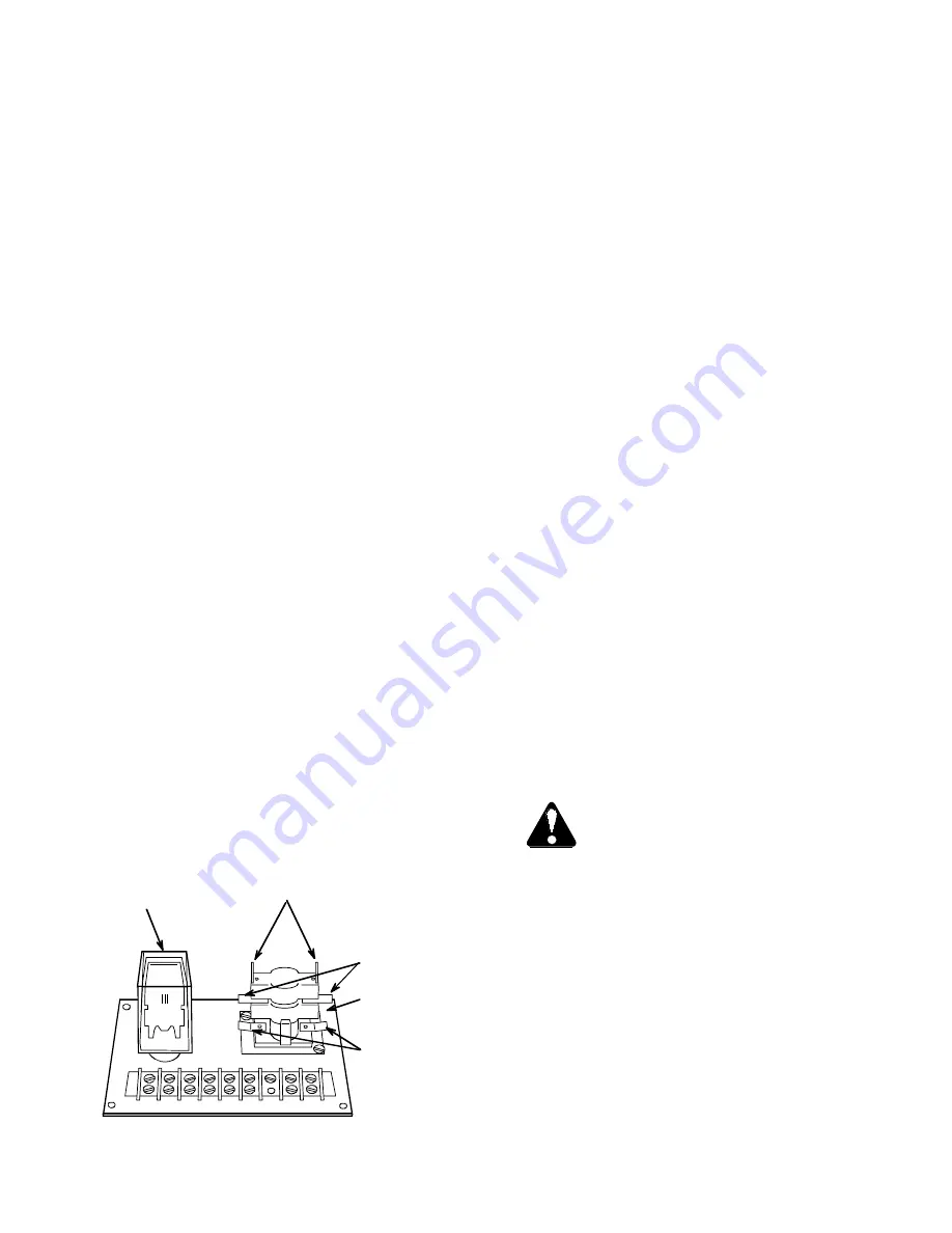
minals 2 and T, thereby energizing the Purge/Lockout
time delay relay. This causes a 15- to 30-second delay
to the ignition while the system is purged of any accu-
mulated gas.
The normally open purge element will close after a 15-
to 30-second delay. The normally closed lockout ele-
ment opens after a 60-second delay. (The lockout ele-
ment should not have to open unless the flame switch
fails to detect heat.) Fig. 7-3 shows the combination
Purge/Lockout relay.
2. After a 15- to 30-second purge period, the purge con-
tacts close PL-021 terminals 1 and 5 and energize the
Burner Control Relay. As the relay energizes, it closes
the holding contacts between PL- 021 terminals 1 and
5, and also terminals 3 and T, supplying voltage to the
Ignition Transformer, No. 2 Gas Solenoid Valve, and
(LP models only) Liquid Solenoid Gas Valve. Burner
should now fire.
3. Shortly after the burner starts, the flame switch
responds to burner heat and OPENS its contacts,
thereby de-energizing the purge and lockout relay ele-
ments. The purge contacts open, but the holding con-
tacts (controlled by the Burner Control Relay) stay
closed to maintain burner operation.
4. The burner will operate on Hi-Fire until the Thermostat
Control circuit opens its contacts and de-energizes the
Hi-Fire gas solenoid valve (No. 1 Gas Valve).
When the Thermostat Control sensor is calling for more
heat and closes its contacts, the Hi-Fire gas solenoid
valve immediately opens; then it cycles as required to
maintain the desired heat.
5. If the burner fails to start due to lack of fuel or malfunc-
tion, and the Ignition Transformer and gas solenoid
valves are known to be energized, then the following
sequence is probably occurring:
A. The flame switch is in the COLD (closed contacts)
state and continues to energize the lockout relay ele-
ment.
B. The lockout relay element trips open after 60 to
120 seconds and cuts off power to the entire dryer via
the Safety Shutdown portion of the control circuit in
Section 8.
C. Once the dryer shuts down, the lockout relay ele-
ment takes several minutes to reset itself.
FAN PROPELLER REMOVAL AND
INSTALLATION
The fan propeller is secured to the motor shaft by the
use of a taper-lock bushing, motor shaft key and three
capscrews. Fig. 7-4 shows a typical cutaway sketch of
the propeller and bushing installation.
CAUTION:
Although the taper-lock method of
retaining the propeller onto the motor shaft is
very simple and obvious, it is essential that the
following points be read carefully and fully
understood, as improper installation can re sult in seri-
ous or fatal injury, caused by a loose, flying propeller.
THREADED BUSHING HOLES
— the threaded holes
within the bushing are provided for disassembly pur-
poses only. See Fig. 7-5. Do not attempt to use these
holes for reassembly, as they will not allow the parts to
become locked onto the shaft, thereby causing a haz-
ardous operating condition.
CLEARANCE HOLES
— When reassembling parts,
the capscrews must be installed through the
UNTAPPED CLEARANCE HOLES, as shown in Fig. 7-
6, to cause the propeller to be pulled forward onto the
tapered bushing, thus locking the parts securely onto
the motor shaft. Refer to text for assembly details.
Whenever any servicing is to be performed which
requires removal and installation of the propeller, make
45
1 1 2 3 4 5 6 L T
PURGE
TERMINALS
(N.O. - 15 to 30 sec. delay on CLOSE)
LOCKOUT
TERMINALS
(N.C. - 60 to 120 sec.
delay on OPEN)
HEATER ELEMENT
TERMINALS
CONTROL RELAY
Part # 044-1014-8
Part # 056-1650-3
PURGE/LOCKOUT
TIME DELAY RELAY
Fig. 7-3 PL-021 Burner control board
Содержание C-2120A
Страница 8: ...6 ...
Страница 18: ...16 ...
Страница 22: ...20 ...
Страница 34: ...32 ...
Страница 38: ...Fig 6 8 ASC control panel internal view 36 Fig 6 7 ASC control panel ...
Страница 39: ...37 Fig 6 9 C 2100A power panel typical 3 phase model shown ...
Страница 44: ...42 ...
Страница 53: ...51 Fig 8 1 C 2100A power circuit 220V 1 phase ...
Страница 54: ...52 Fig 8 2 C 2100A power circuit 220V 3 phase models ...
Страница 55: ...53 Fig 8 3 C 2100A power circuit 440V 3 phase models ...
Страница 56: ...54 Fig 8 4 C 2100A general control circuit p 1 of 3 ...
Страница 57: ...55 Fig 8 4 C 2100A general control circuit p 2 of 3 ...
Страница 58: ...56 Fig 8 4 C 2100A general control circuit p 3 of 3 ...
Страница 59: ...57 Fig 8 5 C 2100A burner control circuit circuit ...
Страница 60: ...58 ...
Страница 66: ...64 ...
Страница 67: ......
Страница 68: ...Division of ffi Corporation 5900 Elmwood Ave Indianapolis IN 46203 1998 ffi Corporation Printed in USA 5 14 98 ...