


13
GB
KJ 45
KJ 45
Revision - 04
Date 10-2008
TOOL IDENTIFICATION
The riveting tool
KJ45
is identifi ed by a label showing the name and
the address of the manufacturer and the model also. If any service is
requested please make reference to the data shown on the label.
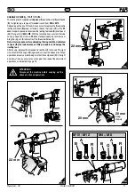
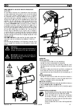
GENERAL NOTES AND USE
The tool can be employed only for threaded inserts
M4÷M12
.
The
KJ45 hydropneumatic system
assures more power than the
pneumatic system used for other models. That means a reduction in the
problems due to the wear and tear of the components, therefore, there
will be an increase in reliability. The technical solutions adopted reduce
the dimensions and the weight of the tool, which is very handy for these
reasons. The possibilities of leakage from the oil-dynamic system, are
eliminated by some sealed gaskets, which solve this problem.
Name and address
of manufacturer
Model
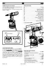
TECHNICAL DATA
• Working pressure
.............................................................
6 - 7 BAR
• Min. int. diam. of the compressed air
feeding
hose
...........................................................
ø min. = 8 mm
• Max free air consumption per cycle ........................................
11 NI
• Force (6 BAR) .......................................................................
28 KN
• Noise level......................................................................
< 75 db(A)
• Weight (with equipment for M10) ..........................................
2.9 Kg
• Working temperature ........................................................
-5°/+50°
• Root mean square in total acceleration
frequency (Ac) to which
the arms are subjected ..............................................
< 2.5 m/sec2
Ø 50
Ø 130
296*
124*
Ø 27
312
M
P
G
E
F
A B C D
L I H N
O
*
with M10 tie rod
MAIN COMPONENTS
A)
.............................................................................. Threaded tie rod
B)
................................................................................................Head
C)
.................................................................. Ring-nut clamping head
D)
.........................................................................Control push-button
E)
.............................................................Compressed air connection
F)
..................................................................... Pressure control valve
G)
............................................................................ Protection bottom
H)
............................................................................. Pneumatic motor
I)
..................................................................................... Oil tank plug
L)
........................................................................Balancer connection
M)
.....................................................................Stroke-adjusting knob
N)
............................................................................... Stroke indicator
O)
..........................................................................Tube carrying head
P)
.................................................................... Forced unscrewing rod
Содержание KJ45
Страница 79: ......