background image

8

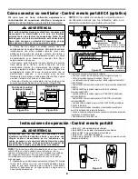
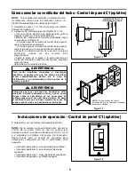
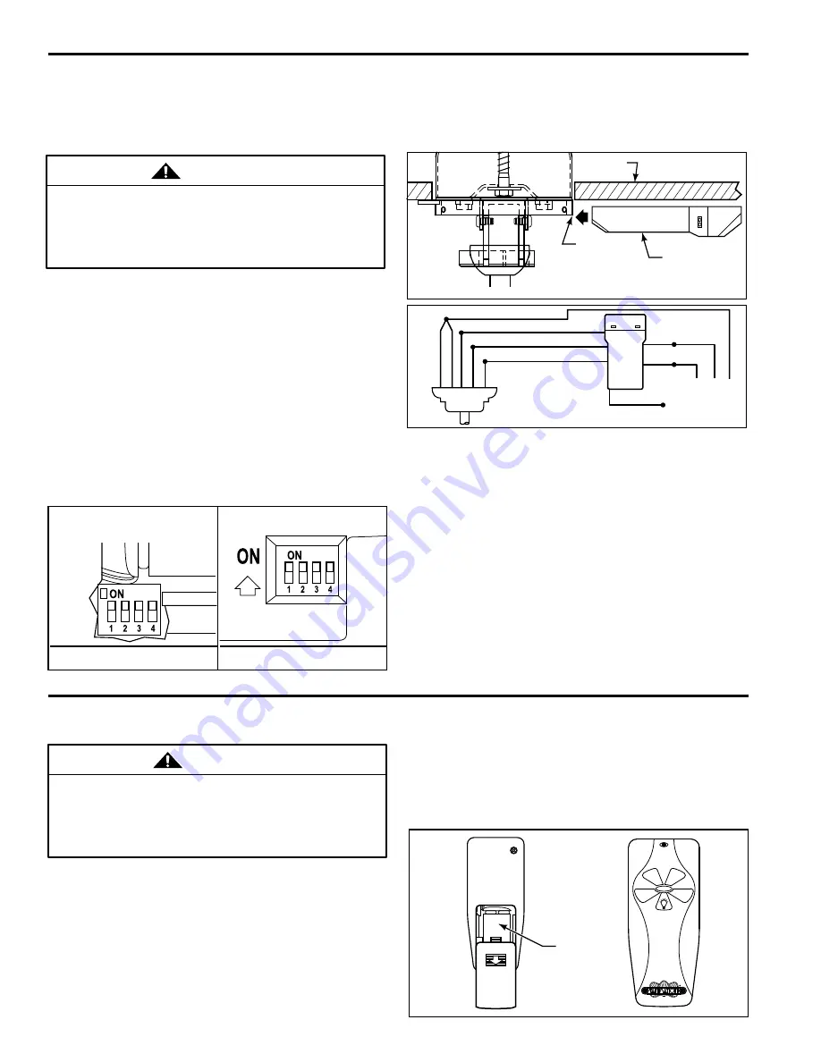
How to Wire Your Fan - C4 Hand-held Remote (Optional)

Figure 10a

Figure 10b

9V

Battery

Receiver Unit Detail

Remote Transmitter

Unit Detail

Operating Instructions - C4 Hand-held Remote (Optional)

OFF

HI

LO

MED

WARNING

Check to see that all connections are tight, including 

ground,  and  that  no  bare  wire  is  visible  at  the  wire 

connectors,  except  for  the  ground  wire.    Do  not 

operate fan until the blades is in place.  Noise and fan 

damage could result.

Figure 13

1. 

Operating & Using Remote Transmitter (Figure 13):

Install  9  volt  battery  (If  not  using  for  long  periods  of 

time,  remove  battery  to  prevent  damage  to 

transmitter).  Store  the  transmitter  away  from  excess 

heat or humidity.

HI Push Button – high fan speed

MED Push Button – medium fan speed

LOW Push Button – low fan speed

OFF Push Button – fan off

Light  Push  Button  –  no  function  (unless  light  kit  is 

installed)

NOTE: Set pull chain to high speed before using the 

remote control.  To avoid accidental pull chain use, 

shorten chain by cutting it 2 to 4 inches below switch 

body. You can now use your speed control to select any 

of the 3-speeds plus OFF.

9V

Battery

WARNING

To avoid possible electrical shock, be sure electricity 

is turned off at the main fuse box before wiring. Note: 

If  you  are  not  sure  if  the  outlet  box  is  grounded, 

contact a licensed electrician for advice, as it must be 

grounded for safe operation. 

If  you  feel  that  you  do  not  have  enough  electrical 
wiring  knowledge  or  experience,  have  your  fan 
installed by a licensed electrician. 

2. 

Installing Receiver in Hanger Bracket:

 Slide remote Receiver into the Hanger Bracket (Figure 11).

 Connect wires as indicated: (Figure 12)

 Green Hanger Bracket and Hanger Ball wires to BARE (ground) 

wire.

 BLACK Receiver Unit wire (AC IN L) to BLACK supply wire.

 WHITE Receiver Unit wire (AC IN N). to WHITE supply wire.

 WHITE Receiver Unit wire (TO MOTOR N) to WHITE fan wire.

 BLACK Receiver Unit wire (TO MOTOR L) to BLACK fan wire.

 BLUE Receiver Unit wire (FOR LIGHT DOWN) to BLUE light wire.

 Position all connected wires and receiver antenna to allow 

installation of ceiling canopy.

 Using canopy screws threaded into the hanger bracket reinstall 

ceiling canopy.

 Restore electrical power.

1.

  Setting  the  Code:  The  remote  unit  has  16  different 

code  combinations.  To  prevent  possible  interference 

from  or  to  other  remote  units  such  as  garage  door 

openers,  car  alarm  or  security  systems,  simply  change 

the  combination  code  in  your  transmitter  and  receiver. 

To set the code, perform these steps.

Transmitter:  remove  battery  cover.    Press  firmly 

below  arrow  and  slide  battery  cover  off.    Slide  code 

switches  to  your  choice  of  up  or  down  position.   

Factory setting is all up. Do not use this position. With 

a small screwdriver or ball point pen slide firmly up or 

down  (Figure  10a).  Replace  battery  cover  on  the 

transmitter.

Receiver:  Slide code switches to the same positions 

as set on your transmitter (Figure 10b).

NOTE:  If fan or supply wires are different colors than 
indicated,  have  this  unit  installed  by  a  qualified 
electrician. 

NOTE: Receiver wires omitted for clarity

CEILING

RECEIVER  UNIT

BRACKET

(Open End)

Figure 11

WH-TO MOTOR N

GRN or BARE-GROUND

GRN from bracket

GRN from hanger ball

WH-AC IN N
BL-AC IN L

BLK-ANT

BLK-TO MOTOR L

BLUE-FOR LIGHT DOWN

Figure 12

120 VAC SUPPLY

(User Supplied)

Содержание Tropicana FP1600 Series

Страница 1: ...he Tropicana Ceiling Fan Net Weight 19 lbs FP1600SO Std Oar Natural Wicker FP1610SO Std Oar White Wicker FP1600NO Nar Oval Natural Wicker FP1610NO Nar Oval White Wicker FP1620NO Nar Oval Natural Wicke...

Страница 2: ...motor fails due to a defect in materials or workmanship during the lifetime of the original purchaser Fanimation will provide the replacement part free of charge when the defective fan is returned to...

Страница 3: ...off each step As each step is completed place a check mark This will ensure that all steps have been completed and will be helpful in finding your place should you be interrupted Unpacking Instructio...

Страница 4: ...ate and untwist the three motor leads Route the motor leads through the Downrod Hanger Ball Assembly 5 Loosen the two setscrews in the downrod support Align the clevis pin holes in the downrod with th...

Страница 5: ...et must seat firmly against outlet box If the outlet box is recessed remove wallboard until bracket contacts box If bracket and or outlet box are not securely attached the fan could wobble or fall WAR...

Страница 6: ...itch and reverse slide switch see page 7 2 Optional fan only wall slide control C1 see page 9 3 Optional fan light remote control C4 see page 8 4 Optional fan light slide wall control C2 or optional 2...

Страница 7: ...on the other side of the outlet box 1 Connect the green grounding lead from the hanger ball and the green grounding lead from the hanger bracket to the supply grounding conductor this may be a bare wi...

Страница 8: ...t Slide remote Receiver into the Hanger Bracket Figure 11 Connect wires as indicated Figure 12 Green Hanger Bracket and Hanger Ball wires to BARE ground wire BLACK Receiver Unit wire AC IN L to BLACK...

Страница 9: ...o high speed before using the wall control To avoid accidental pull chain use shorten chain by cutting it 2 to 4 inches below switch body You can now use your speed control to select any of the 3 spee...

Страница 10: ...Rubber Flywheel using the 10 32 x 1 2 Flywheel Screws Figure 17 2 Make sure the screws securing the Blades to the Flywheel are tight and that the Blades are properly seated on the Flywheel Attach the...

Страница 11: ...If holders are seated incorrectly loosen the screws and retighten 5 Tighten the hanger bracket screws to the outlet box and secure outlet box 6 Interchanging position of fan blades can redistribute th...

Страница 12: ...2 5 6 Hardware Bag Containing HDWFP1600 HDWFP1600 Ref No Parts List Model FP1600 1610 1620 Description FP1600 or FP1610 FP1620 Hanger Bracket Ceiling Canopy with Canopy Wicker Cover 1 3 Part P1608NA...

Страница 13: ...17 6 7 4 5 19 3 2 1 1A The Tropicana FP1600 1610 1620 Exploded View Figure 18 NOTE The illustration shown is not to scale or its actual configuration may vary the wicker is removed for parts clarity G...

Страница 14: ...945 Monument Dr Lebanon IN 46052 888 567 2055 FAX 765 482 5215 Visit Our Website www fanimation com 2002 08 Copyright 2002 Fanimation...

Страница 15: ...ho Peso neto 8 5 kg 19 lb FP1600SO Remo est ndar mimbre natural FP1610SO Remo est ndar mimbre blanco FP1600NO Ovalada estrecha mimbre natural FP1610NO Ovalada estrecha mimbre blanco FP1620NO Ovalada e...

Страница 16: ...para usar con este producto podr a resultar en lesiones personales o da os materiales ADVERTENCIA Para reducir el riesgo de lesiones personales no doble la pesta a del aspa retenedor al instalar equi...

Страница 17: ...cada paso Ponga una marca a medida que vaya completando los pasos De esta forma se asegurar que se hayan completado todos los pasos y ser til para volver al lugar donde estaba en caso de interrupci n...

Страница 18: ...are y desenrolle los tres cables del motor Tienda los cables del motor a trav s del conjunto de barra de bajada cubeta de suspensi n 5 Afloje los dos tornillos de fijaci n en el soporte de la barra de...

Страница 19: ...onecte las aspas del ventilador hasta que el ventilador no est completamente instalado Al colgar el ventilador con las aspas conectadas se pueden da ar las mismas ADVERTENCIA C mo colgar el ventilador...

Страница 20: ...na 7 2 Control deslizante optativo de pared para s lo 3 Control remoto optativo de ventilador y l mpara C4 vea la p gina 8 4 Control deslizante de pared de ventilador y l mpara optativo C2 o control d...

Страница 21: ...los cables blanco y verde en un lado de la caja de distribuci n y los cables negro y azul en el otro lado de la misma 1 Conecte el cable de tierra verde de la cubeta de suspensi n y el cable de tierr...

Страница 22: ...DOWN al cable de AZUL de la l mpara Coloque todos los cables conectados y la antena del receptor para permitir la instalaci n de la cubierta del techo Vuelva a instalar la cubierta del techo usando l...

Страница 23: ...dente acorte la cadena cort ndola de 2 5 a 5 cm 2 a 4 pulgadas por debajo del cuerpo del interruptor Ahora puede usar el control de velocidad para seleccionar cualquiera de las 3 velocidades m s apaga...

Страница 24: ...spas use los agujeros marcados con el n mero 4 NOTA DE INSTALACI N DE ASPA TORNILLOS 2 por aspa VOLANTE Figura 17 La limpieza peri dica de su nuevo ventilador del techo es el nico mantenimiento necesa...

Страница 25: ...ficie del volante Si los retenedores est n mal asentados afloje los tornillos y vuelva a apretarlos 5 Apriete los tornillos del soporte colgante a la caja de distribuci n y sujete la caja de distribuc...

Страница 26: ...piezas Modelo No FP1600 1610 1620 Descripci n FP1600 o FP1610 FP1620 Soporte colgante Cubierta del techo con tapa de mimbre de la cubierta 1 3 No de pieza P1608NA MC P1608WH WH P1608NA RS Estrecha ov...

Страница 27: ...1 1A The Tropicana FP1600 1610 1620 Vista desarrollada Figura 18 11 NOTA La ilustraci n mostrada no est a la escala o su configuraci n real puede variar se ha quitado el mimbre para mayor claridad de...

Страница 28: ...945 Monument Dr Lebanon IN 46052 888 567 2055 FAX 765 482 5215 Visite nuestro sitio web en www fanimation com 2002 10 S Copyright 2002 Fanimation...

Страница 29: ...Ventilateur de plafond Poids net 19 lb FP1600SO Std Aviron Osier naturel FP1610SO Std Aviron Osier blanc FP1600NO troit Ovale Osier naturel FP1610NO troit Ovale Osier blanc FP1620NO troit Ovale Osier...

Страница 30: ...entre les pales rotatives du ventilateur 1 GARANTIE VIE LIMIT E DU MOTEUR Si une partie du moteur du ventilateur ne fonctionne plus par suite d une d fectuosit de mat riau ou de main d uvre pendant l...

Страница 31: ...eur par un lectricien agr MISE EN GARDE 1 V rifier si vous avez re u les pi ces suivantes Pour plus de commodit cocher chaque tape Chaque fois qu une tape est termin e la cocher Vous serez ainsi assur...

Страница 32: ...Pour r duire le risque de blessure personnelle ne pas plier les supports des pales pour installer quilibrer ou nettoyer le ventilateur Ne pas ins rer d objets trangers entre les pales rotatives du ven...

Страница 33: ...as connecter les pales du ventilateur tant que l installation du ventilateur n est pas finie Si on accroche le ventilateur avec les pales on risque d endommager les pales MISE EN GARDE Comment accroch...

Страница 34: ...t C1 voir page 9 3 En option commande distance pour le ventilateur et l clairage C4 voir page 8 4 En option commande murale glissi re pour ventilateur et clairage C2 ou en option deux commandes murale...

Страница 35: ...du bruit et pourrait s endommager Pour installer une commande d clairage en option distincte il est n cessaire d utiliser une autre borne dans la bo te prises Dans ce cas l le fil bleu du ventilateur...

Страница 36: ...qu Figure 12 Les fils verts du support de suspension et de la sph re de support avec le fil D NUD mise la terre Le fil NOIR du r cepteur c a sous tension AC IN L au fil NOIR du circuit d alimentation...

Страница 37: ...irette la vitesse rapide avant d utiliser la commande murale Pour viter une utilisation accidentelle de la tirette la raccourcir en la coupant entre 5 et 10 cm 2 4 po sous le corps de l interrupteur V...

Страница 38: ...ond Pour nettoyer utiliser seulement une brosse douce ou un chiffon non pelucheux pour viter de rayer le fini Les agents de nettoyage abrasifs ne sont pas n cessaires et il faut les viter pour ne pas...

Страница 39: ...mis correctement desserrer les vis et les resserrer 5 Serrer les vis du support de suspension la bo te prises et bien fixer la bo te prises 6 Le fait d intervertir la position des pales du ventilateur...

Страница 40: ...1606NA RS Aviron standard Blanc 5 TRW4WH WH TRW4NA MC MCCRS TRW4NA RS TRW7NA MC TRW7WH WH N A N A N A Comment commander les pi ces Pour commander des pi ces de remplacement fournir les renseignements...

Страница 41: ...19 3 2 1 1A The Tropicana FP1600 1610 1620 Vue clat e Figure 18 REMARQUE L illustration montr e n est pas l chelle et la configuration r elle peut varier l osier est enlev pour plus de clart 11 Fil d...

Страница 42: ...945 Monument Dr Lebanon IN 46052 888 567 2055 FAX 765 482 5215 Visitez notre site Web www fanimation com 2002 10 F Copyright 2002 Fanimation...

Отзывы: