19
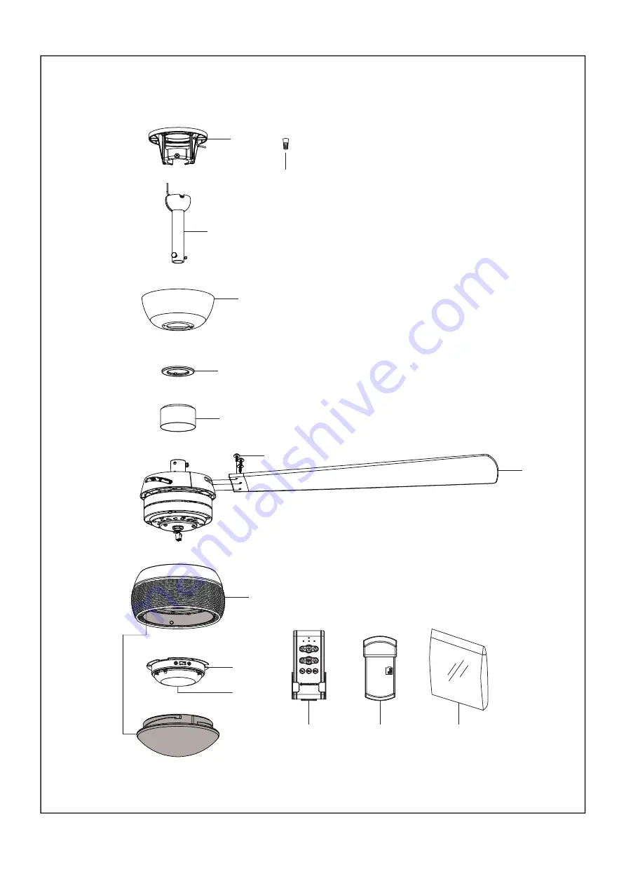
NOTE: The illustration shown is not to scale or its actual configuration may vary.
Product/parts are subject to change without notice.
Model FP6837BSMW
Exploded-View Illustration
Paget
TM
10
12
11
1
2
3
4
5
6
7
9
8a
8b
Страница 1: ...IONS Net Weight 13 45 lbs 6 10 kgs For best and quickest service please provide date code You can find the date code on the carton hand held remote inside of the battery compartment receiver or top of...
Страница 2: ...r supply If the conductor of a fan is identified for equipment grounding then it should be connected to an equipment grounding conductor WARNING TO REDUCE THE RISK OF ELECTRIC SHOCK THIS FAN MUST BE I...
Страница 3: ...right to modify or discontinue any product at any time and may substitute any part under this warranty 8 Under no circumstances may a fan be returned without prior authorization from Fanimation The r...
Страница 4: ...u be interrupted Unpacking Instructions Hanger Bracket Assembly 1 Motor Coupling Cover Assembly 1 Hardware Bags Motor Assembly 1 LED Kit 1 Blade Set 1 Ceiling Canopy 1 Canopy Screw Cover Assembly 1 Re...
Страница 5: ...ation Retailer for optional mounting accessories Turn Off When Not in the Room Ceiling fans cool people not rooms If the room is unoccupied turn off the ceiling fan to save energy Energy Efficient Use...
Страница 6: ...mmonly used for the support of luminaires are not acceptable for fan support and may need to be replaced consult a qualified electrician if in doubt WARNING Turning off wall switch is not sufficient T...
Страница 7: ...downrod into the downrod support on top of the motor Install the clevis pin by aligning the holes in the downrod support with holes in the downrod Secure clevis pin with hairpin clip Tighten the two...
Страница 8: ...the hanger ball A loose set screw could cause fan wobble Figure 6 7 Cut off excess lead wire approximately 6 to 9 inches above top of the downrod Strip insulation off 1 2 inch from the end of each le...
Страница 9: ...sult in damage to the fan blades WARNING To reduce the risk of personal injury do not bend the blades when installing balancing or cleaning the fan Do not insert foreign objects in between the rotatin...
Страница 10: ...it Figure 4 WARNING The color label on these two connectors must correspond to each other 5 Assemble the LED kit to the housing assembly using the two key slots Replace the previously removed screw an...
Страница 11: ...s lined up with tab on the hanger bracket Figure 3 2 Pull the electric wires in the outlet box down through the opening in the hanger bracket and bend wires up and out of the way so that the hanger ba...
Страница 12: ...e remote and receiver NOTE If you are not sure if the outlet box is grounded contact a licensed electrician for advice as it must be grounded for safe operation CAUTION INCORRECT WIRE CONNECTION WILL...
Страница 13: ...RF ANTENNA BLACK WHITE L N AC POWER RED L1 BLUE WHITE LIGHT KIT AC MOTOR GROUND GREEN BLUE BLACK WHITE BLACK BLUE BLACK WHITE WHITE HANGER BRACKET HANGER BALL Figure 4 x 7 Wire Connectors HARDWARE USE...
Страница 14: ...lder screw in hanger bracket taking care not to pinch the wires Tighten shoulder screw Fully assemble and tighten second shoulder screw that was previously removed Figure 1 2 Securely attach and tight...
Страница 15: ...ay from excessive heat or humidly Figure 3 12V 23A Battery 1 pcs Figure 3 4 To set the remote code in the same positions as the receiver use a small screwdriver or ball point pen neither included to s...
Страница 16: ...and the fan and light will turn off after 6 hours 5 Remote functions Figure 5 Figure 5 Reverse Switch Information Season Rotation Direction Counterclockwise Clockwise Switch Position Left Right Summer...
Страница 17: ...n 2 Loose power line connections to the fan or loose switch wire connections in the switch housing 3 Dead battery in remote control 4 Make sure reverse switch position is all the way to one side 4 Rev...
Страница 18: ...83708 8 Light Kit Glass Assembly AP683704OP 9 Hand held Remote TR500 10 Receiver RCCA050050014 11 HDWFP6837BSMW 12 Hardware Bag Containing Wire Connectors 4 3 16 24 Truss Head Screw with Spring Washer...
Страница 19: ...illustration shown is not to scale or its actual configuration may vary Product parts are subject to change without notice Model FP6837BSMW Exploded View Illustration Paget TM 10 12 11 12 1 2 3 4 5 6...
Страница 20: ...2024 01 V 01 Copyright 2024 Fanimation 10983 Bennett Parkway Zionsville IN 46077 Phone 888 567 2055 Outside U S 317 733 4113 FAX 866 482 5215 FANIMATION COM...
Страница 21: ...r favor suministre el c digo de fecha Puede encontrar el c digo de fecha en el paquete en el mando a distancia dentro del compartimento de las pilas en el receptor o en la parte superior de la carcasa...
Страница 22: ...ntilador en funcionamiento ADVERTENCIA No utilice este ventilador con un controlador variable de pared Rheostat o un regulador de intensidad Si lo hiciera podr a da ar la unidad del mando a distancia...
Страница 23: ...animation no se har responsable de los da os que resulten del embalaje incorrecto del producto 9 Se entiende que las reparaciones y las sustituciones son el nico recurso disponible de Fanimation No ex...
Страница 24: ...el mismo La sustituci n de piezas o accesorios que Fanimation no design para usar con este producto podr a ocasionar lesiones personales o da os en el ventilador P ngase en contacto con su tienda si f...
Страница 25: ...para un flujo de aire ptimo Consulte en su tienda minorista de Fanimation para obtener accesorios de montaje opcionales Apague el ventilador cuando no se encuentre en la habitaci n Los ventiladores so...
Страница 26: ...soporte de l mparas no son aptas para soporte de ventiladores y es posible que deban reemplazarse Consulte a un electricista calificado si tiene dudas ADVERTENCIA Apagar el interruptor de pared no es...
Страница 27: ...al de soporte para techo a trav s de la varilla Introduzca los cables de color negro blanco y azul a trav s de la varilla Figura 3 4 Coloque el soporte de la varilla y alinee los orificios de la clavi...
Страница 28: ...ci n est flojo podr a provocar oscilaci n del ventilador Figura 6 7 Corte el exceso de cable aproximadamente de 15 a 23 cm 6 a 9 pulgadas por encima de la parte superior del barral Pele 1 2 cm 1 2 del...
Страница 29: ...otor 3 16 24 Tornillo de cabeza troncoc nica con arandela de resorte arandela plana 3 cada uno por aspa x 9 3 16 24 Tornillo de cabeza troncoc nica con arandela de resorte arandela plana Aditamentos u...
Страница 30: ...nillos Figura 2 Figura 1 Figura 2 PRECAUCI N A fin de reducir el riesgo descargas el ctricas desconecte el circuito de suministro el ctrico al ventilador antes de instalar el kit de iluminaci n 3 Extr...
Страница 31: ...tirados previamente y asegure los tres tornillos Figura 5 Unidad de carcasa Kit LED Figura 5 PRECAUCI N La fuente de luz est dise ado para esta aplicaci n espec fica y puede recalentarse si reparado p...
Страница 32: ...bles NOTA Si no est seguro de si la caja de salida tiene conexi n a tierra pida consejo a un electricista certificado ya que debe tener conexi n a tierra para un funcionamiento seguro ADVERTENCIA Para...
Страница 33: ...Figura 4 Aseg rese de que la ranura en la semiesfera est alineada con el reborde del soporte de suspensi n Figura 3 C mo colgar el ventilador de techo cont ADVERTENCIA Si no coloca la leng eta en la r...
Страница 34: ...est seguro de si la caja de salida tiene conexi n a tierra pida consejo a un electricista certificado ya que debe tener conexi n a tierra para un funcionamiento seguro PRECAUCI N UNA CONEXI N INCORRE...
Страница 35: ...entilador con el conector de cables incluido con la unidad receptora Conecte el conductor negro de la unidad receptora marcado TO MOTOR L al conductor negro del ventilador con el conector de cables qu...
Страница 36: ...uctores hacia arriba y con cuidado col quelos dentro de la caja de salida con los conductores blancos y verdes hacia un lado y los conductores negros hacia el otro Figura 5 Figura 5 Conductor verde de...
Страница 37: ...rnillos de reborde de la abrazadera para colgar mediante el mecanismo de seguro por giro del chavetero Figura 2 Figura 2 Figura 1 Capuch n de techo Cubierta para el tornillo del capuch n Tornillo de r...
Страница 38: ...do a distancia incluido en este ventilador tiene 32 combinaciones diferentes de c digos Para evitar posibles interferencias desde o hacia otros mandos a distancia modifique el c digo de combinaci n de...
Страница 39: ...3 hora Pulse y tanto el ventilador y la iluminaci n se apagar n tras 6 hora 5 Funciones del control remoto Figura 5 Figura 5 6 Si quiere que el flujo del aire vaya en la direcci n opuesta apague el ve...
Страница 40: ...lo un cepillo suave o un pa o sin pelusas para evitar rayar el acabado No se requieren agentes abrasivos de limpieza los mismos deben evitarse para prevenir da os en el acabado Se recomienda limpiar e...
Страница 41: ...ruptor no produzcan ruido al rozar unos con otros o al rozar la pared interior de la caja del interruptor 3 Los conectores de cables dentro de la caja hacen ruido 1 Las aspas no est n sujetas al venti...
Страница 42: ...les 4 3 16 24 Tornillo de cabeza troncoc nica con arandela de resorte arandela plana 10 Bolsa de accesorios para el montaje de aspas que contiene AP255BL ADR1 6BS PG155BS AP260BS APPAC1406BS AP683703M...
Страница 43: ...odelo FP6837BSMW Ilustraci n del despiece Paget TM NOTA La ilustraci n que se muestra no est hecha a escala y su configuraci n real y o terminaci n puede variar 43 10 12 11 12 1 2 3 4 5 6 12 7 9 8a 8b...
Страница 44: ...Copyright 2024 Fanimation 10983 Bennett Parkway Zionsville IN 46077 Llame sin cargo al 888 567 2055 FAX 866 482 5215 Desde fuera de los EE UU llame al 317 733 4113 Visite nuestro sitio Web en www fan...