A
A
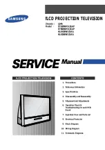
310 lbs Maximum User Capacity
310 lbs Maximum User Capacity
Overhead Anchorage
Non-Overhead Anchorage
C
C
B
B
D
D
E
F
E
G
F
H
2½
ft
5
ft
1½
ft
3½
ft
1
ft
2½
ft
5
ft
1
ft
1½
ft
13½
ft
SRD Deceleration Distance
Free Fall Distance due to Below D-ring Anchorage Condition
Safety factor
Additional Deceleration due to below D-ring Attachment
D-ring shift and harness stretch
SRD Deceleration Distance
Sub Total- Minimum Required Fall Clearance-
for direct overhead use of SRD with No Swing Fall
(sum of A, B and C only)
D-ring Shift and Harness Stretch
Safety Factor
Sub Total- Minimum Required Fall Clearance-
for Non-overhead use of SRD with No Swing Fall
(sum of A through E only)
*Additional Fall Clearance Calculation due to Swing Fall
(using Chart 1)
*Additional Fall Clearance Calculation due to Swing Fall
(using Chart 1)
Total Required Fall Clearance
Including sub-total D and Swing Fall E (from Chart 1)
Total Required Fall Clearance
Including sub-total F and Swing Fall G (from Chart 1)
Figure 3A:
6’ Mini SRD Minimum Required Fall Clearance
Figure 3B:
6’ Mini SRD Minimum Required Fall Clearance
DS6M3A
.1
DS6M3B.1
TS6M3A
.1
* Use Chart 1 to calculate Additional Fall Clearance due to Swing Fall
* Use Chart 1 to calculate Additional Fall Clearance due to Swing Fall
TS6M3B.1
1. Overhead Anchorage 2. Walking/Working Surface 3. Nearest Lower Level or Obstruction
1. Overhead Anchorage 2. Walking/Working Surface 3. Nearest Lower Level or Obstruction
APPENDIX A
010819