


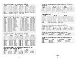


25
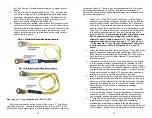
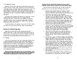
7. Wrap the anchorage end of the
WrapTech
SAL around the
structural member, rotate the barrel on the Anchorage-End
Carabiner and open the gate. Pass the leg webbing of your SAL
through the gate and release the gate so that it is closed and
locked. Make sure the carabiner is positioned so that no edge or
corner of the structural member is able to force the gate open in
the event of a fall. See Figures 3.6 and 3.7 below.
8. For Sliding-D Tie-Back SAL’s, wrap the anchorage end of the
lanyard leg around the structural member. Depress the keeper
on the snap hook and open the gate. Attach the snap hook to
the sliding D-ring on the leg webbing of your SAL and release
the gate so that it is closed and locked. Make sure the snap
hook is positioned so that no edge or corner of the structural
member is able to force the gate open in the event of a fall.
9. Check to ensure that your tie-back SAL is not able to slide off of
either end of the structural member to which you are anchored.
If tied-back to a vertical or diagonal member, ensure that lanyard
is tied back directly above another horizontal member or a
structural element that will prevent the SAL from sliding in the
event of a fall.
10. You are now tied-off and protected by your
WrapTech
or Sliding-
D SAL. Proceed with your work, moving carefully and
deliberately while being aware of slipping, tripping and snagging
hazards. Be aware that the SAL is only six feet long, and any of
these may cause you to loose your footing, resulting in a
possible fall.
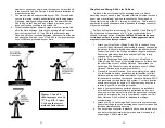
Fig 3.6 Fig 3.7
Correct Tie-Back Connection Incorrect Tie-Back Connection
26
Ironman Shock-Absorbing Lanyards for Extended Free Fall
FallTech Ironman SAL’s (model series 7248, 7248, 8247 and 8248)
are designed to allow up to twelve feet of free fall for those
circumstances where an overhead anchorage may not be available,
leaving the walking/working surface as the only viable option for an
anchor point.
Tying off below the level of the back D-ring on your
FBH or at the foot level should always be a last resort as additional
fall clearance is required, and there is a greater risk of swing fall
injuries.
Never use any Shock-Absorbing Lanyards in a system that allows
more than 6 feet of free fall, unless this application is specifically allowed
on the product label. Use of an SAL that is not rated for this application
may result in serious injury or death.
1. Attach
the
Ironman
SAL to the back D-ring of your Full Body
Harness by depressing the keeper and opening the gate on the
double-locking snap hook at the attachment end. Connect the
hook to the D-ring and release the gate and keeper. Ensure the
gate closes and locks and that the D-ring is fully engaged by the
snap hook.
2. Attach the Anchorage-End Connector of your SAL to one of the
lanyard keepers on either end of the chest strap of your Full
Body Harness. Never attach the Anchorage-End Connector to
any other point on your Full Body Harness: Serious injury or
death could result.
3. Proceed to your work location. If you are working in the vicinity
of a fall hazard, calculate possible swing fall hazards, total fall
distance, and required clearance distance. If you have a swing-
fall hazard or do not have the required clearance distance, STOP
and reevaluate your application and system. Your work location
should never exceed an angle of 15 degrees in any direction in
relation to your SAL’s anchorage location or locations.
4. Inspect your anchorage connectors(s) and ensure installation is
in accordance with the manufacturer’s instructions, and so as to
allow no more than twleve feet of free fall (the anchorage
connector should be at or above the level of your back D-ring on
your Full Body Harness. See Section 5 for additional anchorage
considerations.
5. Attach your SAL’s Anchorage-End Connector to your anchorage.
Ensure that the gate on the anchorage-end connector closes and
latches automatically and securely.
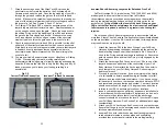
6. Ironman SAL’s with rebar hooks may be attached to properly-
rated structural members such as pipes and scaffolding,
provided they are horizontal relative to the walking/working


