


19
in applications where the user may be exposed to an electrical arc
hazard.
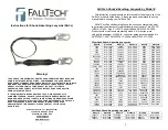
Tie-Back:
FallTech’s WrapTech
line of SAL’s is designed to be used in
applications where there may not be an anchorage connector available.
WrapTech
SAL’s utilize an anchorage-end carabiner with a 5,000 lb
gate, and may be wrapped around a properly rated structural member
with the carabiner fastened to the leg webbing to create the connection.
WrapTech
SAL’s are denoted by model numbers beginning with 7241 or
8241.
FallTech
SAL’s which have a sliding D-ring on the lanyard leg or
legs may also be used for tie-back applications (these are denoted by
the presence of a “D” in the model number).
3.5: Instructions for use by type
Before using any Shock-Absorbing Lanyard, read and understand
instructions, warnings and labels for each component of your PFAS and
inspect each component, including this SAL, prior to use and in
accordance with manufacturer’s instructions. Don and properly adjust
your Full Body Harness.
Select the appropriate Shock Absorbing Lanyard for your application,
based on the conditions on your job-site and the specific fall hazards that
you will encounter. If you are unsure as to which SAL or SAL’s may be
correct for your application or applications, seek the assistance of a
competent person or contact FallTech for assistance.
Warning: Shock Absorbing Lanyards should only be attached to
the back D-ring of your Full Body Harness. Never attach an SAL to
side or hip D-rings, shoulder D-rings or to front or chest D-rings.
This may result in serious injury or death.
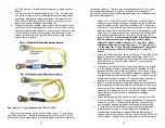
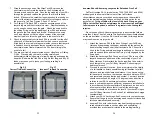
ClearPack, SoftPack and Internal/ElasTech SAL’s
:
ClearPack
and SoftPack SAL’s feature the traditional style “pack-
style” shock-absorber on one end of the SAL. This is the Attachment
End of the SAL and should be connected to the back D-ring of your Full
Body Harness using the double-locking snap hook directly adjacent to
the shock absorber. The snap hook, rebar hook or carabiner located at
the opposite end or ends of the SAL are your Anchorage-End
Connectors which are to be attached to the anchorage element of your
PFAS. See Figure 3.1 below.
Internal
and
ElasTech
SAL’s feature an “Internal-style” shock-
absorber. These SAL’s use a tubular webbing containing a full-length
shock absorber which elongates in the event of a fall. The Attachment-
20
End Connector is adjacent to the “scrunched” end of the tubular
webbing, which can also be identified by the presence of the labels and
label cover. This end attaches to the back D-ring of your Full Body
harness, while the snap hook, rebar hook or carabiner at the opposite
end or ends is your Anchorage-End Connector. See Figure 3.2 Below.
All ClearPack, SoftPack and Internal/ElasTech SAL’s are rated
for a maximum free fall of 6’ (six feet) and have a maximum capacity
of 310 lbs. (user, clothing, tools and equipment). FallTech
HeavyWeight SAL’s (model series 7246 and 8246) are rated for a
maximum capacity of 425 lbs (user, clothing, tools and equipment).
1. Attach the SAL to the back D-ring of your Full Body Harness by
depressing the keeper and opening the gate on the double-
locking snap hook at the attachment end. Connect the hook to
the D-ring and release the gate and keeper. Ensure the gate
closes and locks and that the D-ring is fully engaged by the snap
hook.
2. Attach the Anchorage-End Connector of your SAL to one of the
lanyard keepers on either end of the chest strap of your Full
Body Harness. Never attach the Anchorage-End Connector to
any other point on your Full Body Harness: Serious injury or
death could result.
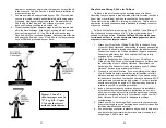
3. Proceed to your work location. If you are working in the vicinity
of a fall hazard, calculate possible swing fall hazards, total fall
distance, and required clearance distance. If you have a swing-
fall hazard or do not have the required clearance distance, STOP
and reevaluate your application and system. Your work location
should never exceed an angle of 15 degrees in any direction in
relation to your SAL’s anchorage location.
4. Inspect your anchorage connector and ensure it is installed in
accordance with the manufacturer’s instructions, and so as to
allow no more than six feet of free fall (the anchorage connector
should be at or above the level of your back D-ring on your Full
Body Harness. See Section 5 for additional anchorage
considerations.
5. Attach your SAL’s Anchorage-End Connector to your anchorage.
Ensure that the gate on the anchorage-end connector closes and
latches automatically and securely.
6. SAL’s with rebar hooks may be attached to properly-rated
structural members such as pipes and scaffolding, provided they
are horizontal relative to the walking/working surface and that the
rebar hook will be unable to slide off the end of the member.
Never attach to a diagonal or vertical structural member or any
anchor point where the rebar hook may slide off in the event of a


