manualshive.com logo in svg
background image

4


These  instructions  are  only  valid  if  the  country  code  appears  on  the 
appliance.  If  the  code  does  not  appear  on  the  appliance,  refer  to  the 
technical instructions for adapting the appliance to the conditions for use 
in that country. 


Installation must meet national or local regulations. Attention must be paid 
to:  safety  (installation  &  use)  regulations,  health  and  safety  at  work  act, 
local and national building regulations, fire precautions act.  


To prevent shocks, all appliances must be earthed. 


This  appliance has been CE-marked on the  basis of  compliance  with  the  
Low  Voltage  and  EMC Directives for the voltages stated on the data plate


This equipment is for professional use only and must be used by qualified 
persons. 


The  installer  must  instruct  the  responsible  person(s)  of  the  correct 
operation and maintenance of the appliance. 


Only competent persons are allowed to service this appliance. 


Unless  otherwise  stated,  parts  which  have  been  protected  by  the 
manufacturer must not be adjusted by the installer. 


Take care when moving an appliance fitted with castors. 


The  appliance  must  be  serviced  regularly  by  a  qualified  person.  Service 
intervals should be agreed with the service provider. 


Check that no damage has occurred to the appliance, power cable, or plug 
during transit. If damage has occurred, do not use this appliance. 


Installation,  periodic  testing,  repair  and  fixed  wiring  connections  should 
only be undertaken by a competent electrician. 


Ensure power cable is routed free from the appliance to avoid damage. 


We  recommend  supplementary  electrical  protection  with  the  use  of  a 
residual current device (RCD) 


The appliance has been designed and approved to use Falcon Kick plates, 
non  Falcon  kick  plates  could  potentially  adversely  affect  the  performance 
of the appliance by restricting the air to the appliance. 


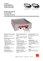
Содержание E9541

Страница 1: ...ion and servicing instructions COUNTERTOP GRIDDLES E9541 E9541CR E9541R E9581 E9581CR E9581R Read these instructions before use T100948 Published 12 05 17 DATE PURCHASED MODEL NUMBER SERIAL NUMBER DEA...

Страница 2: ...iance and any replacement parts in a safe manner via a licensed waste handler Appliances are designed to be dismantled easily and recycling of all material is encouraged whenever practicable Dear Cust...

Страница 3: ...3 SYMBOLS SPANNER SCREWDRIVER COOKING OIL GREASE SPARK IGNITION FLAME WARNING VIEWPORT ALLEN KEY IGNITER C SPANNER...

Страница 4: ...enance of the appliance Only competent persons are allowed to service this appliance Unless otherwise stated parts which have been protected by the manufacturer must not be adjusted by the installer T...

Страница 5: ...G CLEARANCES 10 6 2 ASSEMBLY 10 6 3 COMMISSIONING 12 6 4 SUITING 13 7 0 SERVICING 15 7 1 CONTROL PANEL REMOVAL 15 7 2 ELEMENT TRAY REMOVAL 16 7 3 OPERATING THERMOSTAT REMOVAL 17 7 4 ELEMENT REMOVAL 18...

Страница 6: ...elevant EU directives for the heat inputs gas pressures and voltages stated on the data plate A Serial No B Model No C Flue Type D Gas Category E Gas Pressure F Gas Type G Gas Rate H Total Heat Input...

Страница 7: ...ontrol to desired setting 2 2 3 To switch the unit off turn temperature control to off position 3 0 CLEANING AND MAINTENANCE 3 1 Turn off and cool down 3 2 Scrape off burnt on food 3 3 Remove other de...

Страница 8: ...Consideration must be given to required draw of current THIS APPLIANCE MUST BE EARTHED Live 1 Phase 1 Brown Live 2 Phase 2 Black Live 3 Phase 3 Grey Neutral Blue Earth Yellow Green E9541 E9541CR E9541...

Страница 9: ...9 5 0 DIMENSIONS CONNECTION LOCATIONS...

Страница 10: ...ot they shall be clad with a suitable non combustible heat insulating material and that the closest attention be paid to fire prevention regulations If suiting the necessary clearances to any combusti...

Страница 11: ...11 6 2 2 Connect appliance to mains supply...

Страница 12: ...s to desired temperature 6 3 8 Ensure amber neon s illuminates 6 3 9 This appliance is also provided with a terminal for connection of an external equipotential conductor This terminal is an effective...

Страница 13: ...rear infill and replace with rear suiting plate and fixings 6 4 4 Remove the front side panel countersunk screw and suiting plate NOTE The DLS system is designed to give a quick and easy suiting solut...

Страница 14: ...t through the front fixing holes of both units 6 4 8 B Left hand unit Slide the penny and lock washer on to the screw and secure using the M5 nut 6 4 9 C Remove the front bolts from feet insert base t...

Страница 15: ...O ENSURE THAT IT IS NOT INADVERTENTLY SWITCHED ON THE GRIDDLE PLATES ON THE E9500 SERIES ELECTRIC GRIDDLES ARE FIXED TO THE HOB PANEL AND ALL SERVICING SHOULD BE CARRIED OUT WITHOUT THE REMOVAL OF THE...

Страница 16: ...ils 7 2 3 Loosen the 2 front M5 nuts holding the element tray 7 2 4 Lift up element tray and slide rearwards 7 2 5 Lower tray free of mounting brackets ensuring thermostat capillaries clear their slot...

Страница 17: ...g screws 7 3 4 Remove element tray as shown in 7 2 7 3 5 Loosen nuts on phial clamps 7 3 6 Carefully pull phial forward free of the clamp 7 3 7 When replacing the phial ensure you re fit the vidaflex...

Страница 18: ...4 2 Remove wiring from element tails 7 4 3 Remove element tray as shown in 7 2 7 4 4 Loosen nuts on rear clamp 7 4 5 Remove nuts and clamps from front centre of element 7 4 6 Slide element forward fr...

Страница 19: ...ary is supported in the two guides and the phial is pushed fully in until it hits the end of the phial clamp before fully tightening the clamp nuts 7 6 SAFETY THERMOSTAT RESET CHROME GRIDDLE ONLY Allo...

Страница 20: ...20 7 7 CIRCUIT DIAGRAMS 7 7 1 E9541 E9541R...

Страница 21: ...21 7 7 2 E9541CR...

Страница 22: ...22 7 7 3 E9581 E9581R...

Страница 23: ...23 7 7 4 E9581CR...

Страница 24: ...24 7 8 WIRING DIAGRAMS 7 8 1 E9541 E9541R...

Страница 25: ...25 7 8 1 E9541CR...

Страница 26: ...26 7 8 1 E9581 E9581R...

Страница 27: ...27 7 8 1 E9581CR...

Страница 28: ...ot enough Faulty thermostat Replace Note when checking plate temperature probe 210mm in from each side halfway between front and rear on E9581 models Probe centre plate on E9541 models 9 0 SPARE PARTS...
Страница 29: ...ATION It is recommended to have a maintenance contract with a local service provider SERVICELINE CONTACT UK only Phone 441438 363 000 Warranty Policy Shortlist For our warranty policy please go to www...
Отзывы: