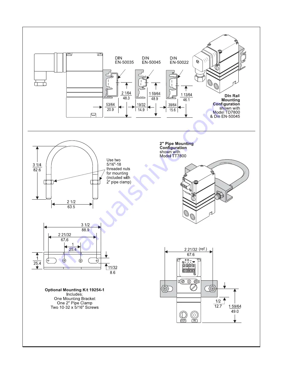
Figure 8.
Optional Mounting Kit 19254-1
(sold separately)
Figure 7.
Din Rail Mounting Kit 16893-1
(included with unit)
5
Страница 1: ...DC input signal to a linearly proportional pneumatic output pressure SPECIFICATIONS Minimum Span 3 15 0 2 1 0 20 100 4 20 mA DC 0 10 VDC 1 9 VDC 0 5 VDC 1 5 VDC 20 120 1 5 8 0 150 800 5 0 35 35 3 27...
Страница 2: ...ltage input units TDFI7800 TAFI7800 TDFN7800 TAFN7800 Class I Division 2 Groups A B C and D Class II Division 2 Groups F and G Class III Division 2 NEMA 4X Enclosure Temperature Code T4 TTFI7800 TRFI7...
Страница 3: ...umalloy Inrare cases igntion sources due to impact and friction sparks couldoccur Thisshallbeconsideredwhentheequipment is installed in locations that specifically require Group II category1Gequipment...
Страница 4: ...Installation continued Figure 6 TR7800 Outline Dimensions Figure 5 TD7800 Outline Dimensions Figure 4 TT7800 Outline Dimensions 4...
Страница 5: ...Figure 8 Optional Mounting Kit 19254 1 sold separately Figure 7 Din Rail Mounting Kit 16893 1 included with unit 5...
Страница 6: ...tream to avoid interference with transducer performance The user is responsible for ensuring that the environmentinwhichtheunit isinstalledand the operating gas are compatible with the materials in th...
Страница 7: ...desiredoutputrangeis obtained SPLIT RANGEOPERATION Lo Hi Span Adjustment 1 Set the Lo Hi Span switch to the Lo position for 3 9 psig or 9 15 psig output range and for 4 20 mA input range Set the Lo Hi...
Страница 8: ...Calibrations Adjustments continued Figure 10 T7800CalibrationConfiguration 8...
Страница 9: ...11 1 12 1 13 14 15 16 17 1 18 19 Qty Cover Machining Screw Screw Gasket Nozzle Body Assembly Orifice Assembly Spring Disk Diaphragm Spacer Ring Diaphragm Assembly Foam Block Valve Body Assembly Screw...
Страница 10: ...n with alcohol and dry with compressed air NOTES 1 Parts must be completely dry before reassembling 2 If the standard maintenance procedure does not correct the problem install the appropriate service...