background image

WiFi access point

WiFi AP-EU
WiFi AP-US

COMMUNICATION SETUP: HBH4 REMOTE 

TERMIN

AL -

2.

 R

EF

. 2004


·29·

CNC8

065

 Co

mmu

n

ication

s

 Test- 

WiFi

 a

c

ce

ss 

po

int

2.6

CNC8065 Communications Test- WiFi access point

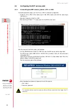
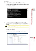
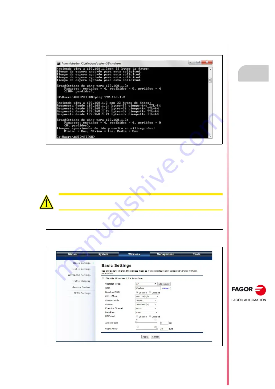
To verify the communications between the CNC8065 and the WiFi access point, do the following:

• Execute "cmd.exe" on the CNC8065.

• Execute "ping 192.168.1.2".

2.7

Hidden Wi-Fi network settings (optional configuration)

Once proper communication has been verified, the WiFi network can be hidden in the WiFi access
point settings.

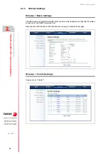
Wireless / Basic Settings

Selecting the SSID Broadcast: Disabled and press [Apply] to validate the changes.

The option to hide the WiFi network offers enhanced security settings, but if there are communication
issues then any assistance will be more complex.

Содержание WiFi AP-EU

Страница 1: ...WIFI ACCESS POINT WiFi AP EU WiFi AP US Installation manual Ref 2004 ...

Страница 2: ...be considered as impossible In any case Fagor Automation shall not be held responsible for any personal injuries or physical damage caused or suffered by the CNC if it is used in any way other than as explained in the related documentation Thecontentofthis manualand its validity for the productdescribed here has been verified Even so involuntary errors are possible hence no absolute match is guara...

Страница 3: ...MOTE TERMINAL CNC8065 2 1 Basic diagram 21 2 2 Installing and connecting the WiFi access point 21 2 3 Configuring the WiFi access point 22 2 3 1 Connecting the WiFi access point to a PC or CNC 22 2 3 2 System configuration 23 2 3 3 Wireless Settings 24 2 4 Obtaining the MAC address of the HBH4 remote terminal 26 2 5 HBH4 terminal settings 27 2 6 CNC8065 Communications Test WiFi access point 29 2 7...

Страница 4: ... 4 WiFi AP EU WiFi AP US REF 2004 ...

Страница 5: ...U PRUH RI WKH IROORZLQJ PHDVXUHV 5HRULHQW RU UHORFDWH WKH UHFHLYLQJ DQWHQQD QFUHDVH WKH VHSDUDWLRQ EHWZHHQ WKH HTXLSPHQW DQG UHFHLYHU RQQHFW WKH HTXLSPHQW LQWR DQ RXWOHW RQ D FLUFXLW GLIIHUHQW IURP WKDW WR ZKLFK WKH UHFHLYHU LV FRQQHFWHG RQVXOW WKH GHDOHU RU DQ H SHULHQFHG UDGLR 79 WHFKQLFLDQ IRU KHOS 7KLV GHYLFH FRPSOLHV ZLWK 3DUW RI WKH 5XOHV 2SHUDWLRQ LV VXEMHFW WR WKH IRO ORZLQJ WZR FRQGLWLRQV...

Страница 6: ......

Страница 7: ...WiFi AP EU WiFi AP US REF 2004 1 7 CHARACTERISTICS AND CONNECTION The WiFi AP EU WiFi AP US is a wireless access point that provides wireless network communication coverage for industrial environments ...

Страница 8: ...8 mm 4 37 x 10 08 x 1 89 Mounting Wall post Weight 0 5 Kg Ambient Operating temperature Without heater 20 70 C 4 158 F Storage temperature 40 70 C 40 158 F Humidity 10 95 non condensing Interface operation modes Access point AP Client Antenna Default 5 dBi external Omni antenna 2 x RP SMA connectors female for RP SMA antenna male Other characteristics Administration Telnet FTP SNMP Web UI Wireless...

Страница 9: ... 23 dBm MCS7 15 802 11gn HT40 26 dBm MCS0 8 22 dBm MCS7 15 Note The indicated value is the target power calibrated on the card Actual power will vary depending on the regulations for each country Receiver sensitivity 802 11b Sensitivity 91 dBm 1 Mbps 85 dBm 11 Mbps 802 11g Sensitivity 89 dBm 6 Mbps 70 dBm 54 Mbps 802 11n HT20 83 dBm MCS0 8 65 dBm MCS7 15 802 11n HT40 80 dBm MCS0 8 62 dBm MCS7 15 1...

Страница 10: ...product package contains the following elements WiFi AP EU or WiFi AP US 2 removable 5dBi antennas 2 post mounting rings Power cable and 24 V DC power supply Ferrite core Ground cable Product CD Post mount ring Ferrite core Power cable and 24 V DC power supply The power cord and power supply supplied with the product must be used Otherwise the WiFi access point could become damaged ...

Страница 11: ...RISTICS AND CONNECTION 1 REF 2004 11 Installing the WiFi access point 1 3 2 Hardware installation Ethernet cable connection 1 Remove the lid from the bottom side as shown in the figure 2 Connect a shielded 6 or 6A STP Ethernet cable to the RJ45 port ...

Страница 12: ...ent over voltages or electrostatic discharges it is important to ground the WiFi access point cables and power supply correctly during normal operation 1 Remove the screw from the grounding connection point at the bottom of the WiFi access point 2 Place the grounding cable and fasten the cable to secure it 3 Slide the lid and press the locking button downward to seal the bottom section Remove the ...

Страница 13: ...ect external antennas 1 Connect the external antennas that come with the package to the SMA connectors on top side of the WiFi access point For improved coverage it is recommended to use greater range antennas The WiFi access point must be turned off before connecting the external antennas The device should not be turned on without having the external antennas connected otherwise it could cause da...

Страница 14: ...an be inclined at 45º to the left and the other antenna 45º to the right Positioning the antennas in this manner is ideal since there is less coupling between them Incline the other antenna another 45º to the right The polarization of the antennas must be aligned correctly The maximum signal strength between both bridges is achieved when they use the same polarization ...

Страница 15: ...in a clockwise direction to attach the antennas 5 To adjust the antennas first loosen the connector in a counterclockwise direction and then adjust the antenna into the desired position Do not bend or turn the antennas without first loosening the connector fastener Otherwise the antennas could become damaged 6 The installation of the antennas is now complete ...

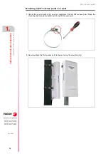
Страница 16: ...ling the WiFi access point Mounting a WiFi access point to a post 1 Unlock the post mounting ring using a screwdriver Flip the WiFi access point Place the mounting ring through the center hole in the WiFi access point 2 Securely attach the WiFi access point to the post using the mounting ring ...

Страница 17: ... US CHARACTERISTICS AND CONNECTION 1 REF 2004 17 Installing the WiFi access point Power supply connection 1 Connect the power cable to the 24 V DC power supply 2 Connect the Ethernet cable leaving the WiFi access point to the power supply ...

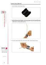
Страница 18: ...ite core by lifting the latches 2 Place the ferrite core around the Ethernet cable at a distance of 2 to 3 inches from the connector between 5 08 and 7 65 centimeters Tests may be required for the final location depending on its effectiveness in reducing high frequencies 3 Loop the cable inside the ferrite core This allows to the core to be fastened in place ...

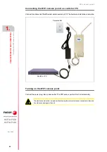
Страница 19: ... US CHARACTERISTICS AND CONNECTION 1 REF 2004 19 Installing the WiFi access point 4 Close the ferrite core by closing the latches 5 Connect the Ethernet cable with the attached ferrite core to the Data in port of the power supply DATA IN ...

Страница 20: ...onnect the other end of the Ethernet cable to a switch or PC The hardware installation is complete Turning on the WiFi access point Connect the power plug into a power outlet The WiFi access point will turn on immediately Power outlet Switch or PC The device should not be turned on without having the external antennas connected otherwise it could cause damage to the unit ...

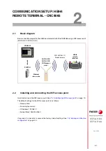
Страница 21: ...int Install and connect the WiFi access point See 1 3 Installing the WiFi access point on page 10 The default settings for the WiFi access point is as follows Name admin Password password IP Address 192 168 1 1 Subnet Mask 255 255 255 0 If required it is possible to recover the factory default settings See 2 8 Backup and Restore configuration on page 30 SWITCH WiFi AP EU WIFI AP US WiFi access poi...

Страница 22: ...92 168 1 1 to verify access to the WiFi access point Start the session in the WiFi access point interface Use any WEB browser on the PC or CNC to access the WiFi access point configuration The WiFi access point WiFi AP EU WiFi AP US provides an easy to use web based management tool Open the web browser and enter the IP address 192 168 1 1 in the address field This is the default address for the Wi...

Страница 23: ...access point 2 3 2 System configuration System Basic settings Select Country Region and press Apply to validate the modifications System Network Settings Configure the following parameters Network Mode Bridge Select static IP Static IP Change IP Address and Subnet Mask if required Press Apply to validate the changes ...

Страница 24: ...s point 2 3 3 Wireless Settings Wireless Basic Settings The WiFi network configured for the WiFi access point must be visible when configuring the wireless connection for the HBH4 remote terminal Selecting the SSID Broadcast Enabled and press Apply to validate the changes Wireless Profile Settings Double click on Profile1 ...

Страница 25: ...password for the WiFi network Wireless Access Control optional settings Configure the parameters as follows Access control mode Allow Listed MAC Address Enter the MAC address displayed on the screen of the HBH4 remote terminal See 2 4 Obtaining the MAC address of the HBH4 remote terminal on page 26 The password cannot be longer than 10 characters The MAC Address option provides greater security se...

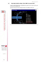
Страница 26: ...the MAC address of the HBH4 remote terminal 2 4 Obtaining the MAC address of the HBH4 remote terminal Access the System Settings menu of the HBH4 remote terminal To do this press and hold a part on the screen not displaying data Select the WiFi option to retrieve the MAC address for the HBH4 remote terminal ...

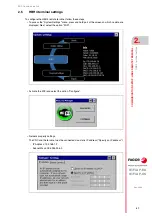
Страница 27: ...te terminal follow these steps To access the System Settings menu press and hold part of the screen on which no data are displayed Next select the option WiFi Activate the WiFi and select the option Configure Network property settings The CNC and the terminal must be connected via a static IP address Specify an IP address IP Address 192 168 1 2 Subnet Mask 255 255 255 0 ...

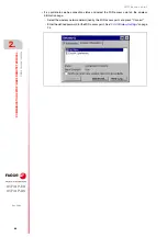
Страница 28: ... terminal settings It is possible to see he connection status and select the WiFi access point on the wireless information page Select the wireless network determined by the WiFi access point and press Connect Enter the defined password for the WiFi access point See 2 3 3 Wireless Settings on page 24 ...

Страница 29: ...owing Execute cmd exe on the CNC8065 Execute ping 192 168 1 2 2 7 Hidden Wi Fi network settings optional configuration Once proper communication has been verified the WiFi network can be hidden in the WiFi access point settings Wireless Basic Settings Selecting the SSID Broadcast Disabled and press Apply to validate the changes The option to hide the WiFi network offers enhanced security settings ...

Страница 30: ...t the session Enter the Management Configuration file menu Management Configuration File This menu allows you to backup the settings as well as to restore the default factory settings or restore a previously saved configuration It is recommended that a backup copy of the configuration Making a backup copy After clicking Save a dialogue box will appear to create a configuration file ap cfg and for ...

Страница 31: ...be deleted and the device will restart The default factory settings will be applied after it has been restarted Reset button If the WiFi access point software is blocked and it is not possible to reset it via the web based management tool it can still be done by pressing the reset button Press and hold the button for at least 5 seconds and release it until the PWR LED flashes The default factory s...

Страница 32: ... 32 WiFi access point WiFi AP EU WiFi AP US 2 COMMUNICATION SETUP HBH4 REMOTE TERMINAL REF 2004 Backup and Restore configuration ...

Страница 33: ...WiFi access point REF 2004 33 ...

Страница 34: ... 34 WiFi access point REF 2004 ...

Страница 35: ......

Страница 36: ...Fagor Automation S Coop Bº San Andrés 19 Apdo 144 E 20500 Arrasate Mondragón Spain Tel 34 943 039 800 Fax 34 943 791 712 E mail info fagorautomation es www fagorautomation com FAGOR AUTOMATION ...

Отзывы: