


EN
9
9
458
650 min.
356
356
341
341
11a
185
2-3
12a
11
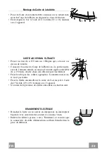
INSTALLATION
Wall drilling and bracket fixing
Wall marking:
• Draw a horizontal line at 650 mm above the hob.
• Mark a reference point at 356 mm from the corner of the wall and 458 above the horizontal
reference line as shown.
• Repeat the operation for the opposite side and check levelling.
• Drill at the points marked, using a ø 12 mm drill bit.
• Insert the bracket plugs
11a
into the holes and screw into place.
• Mark a reference point at 1-2 mm below the ceiling or top limit and at 341 mm from the
corner of the wall as shown. Repeat the operation for the opposite side and check levelling.
• Drill at the points marked, using a ø 8 mm drill bit.
• Insert the wall plugs
11
in the holes.
• Fix the brackets using the
12a
screws (4,2 x 44,4) supplied.
• Mark a reference point at 185 mm below the newly fixed bracket and at 341 mm from the
corner of the wall as shown. Repeat the operation for the opposite side and check levelling.
• Drill at the points marked, using a ø 8 mm drill bit.
• Insert the wall plugs
11
in the holes.
• Fix the brackets using the
12a
screws (4,2 x 44,4) supplied.
Содержание WEST ANGOLO BIANCO SC
Страница 8: ...EN 8 8 Dimensions...
Страница 19: ...FR 1 9 19 Encombrement...
Страница 30: ...DE 3 0 30 Platzbedarf...
Страница 41: ...ES 4 1 41 Dimensiones...
Страница 48: ...GR 4 8 48 650 mm 120 mm...
Страница 49: ...GR 4 9 49 0 04 mbar 8...
Страница 50: ...GR 5 0 50...
Страница 52: ...GR 5 2 52...
Страница 55: ...GR 5 5 55 10 4 12n 3 5 x 16 10 12f 1 12n 10 150 150 8 2 12e 2 9 x 9 5 8 12e 150 3 mm...
Страница 56: ...GR 5 6 56 1 1 0 1 0 2 3 L M V L M V 1 2 3...
Страница 57: ...GR 5 7 57 2 4 A B A B...
Страница 59: ...RU 5 9 59 650 I 120...
Страница 60: ...RU 6 0 60 0 04 8...
Страница 61: ...RU 6 1 61...
Страница 63: ...RU 6 3 63...
Страница 65: ...RU 6 5 65 20 6 12g 7 2 1 2 12c 20 12g 2 2 2 1 12c 12b Vr 11a 11 Vr 11 12 11a Vr 150 120 120 9 150 120 9...
Страница 66: ...RU 6 6 66 10 4 12n 3 5 x 16 10 12f 1 12n 10 150 150 8 2 12e 2 9 x 9 5 8 12e 150 3...
Страница 67: ...RU 6 7 67 1 1 0 1 0 2 3 L M V L M V 1 2 3...
Страница 68: ...RU 6 8 68 2 4 A B...
Страница 74: ...PL 7 4 74 Wymiary...
Страница 81: ......
Страница 82: ......
Страница 83: ......
Страница 84: ...991 0432 061_ver5 190426 D000000002611_02...


