


3.
Remove the cover from the field wiring compartment.
Remove the wiring electrical knockout using a flat-blade
screwdriver. Feed the Power Supply Cable through the
electrical knockout.
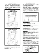
4.
Rotate the two adjustment screws ( R in FIGURE 8 )
until inserted halfway in the slot. Hang the canopy on the
bracket. The canopy hangs from the flanges on the lower
bracket. Due to the weight of the canopy, two people should
lift it to avoid injuries. Make sure that the tabs are fully inserted
into the slots and that the canopy is secure on the bracket.
5.
The height of the canopy can be adjusted by rotating
the two screws (R) indicated in FIGURE 8. These are also
used to insure that the canopy is level.
Version 11/00 - Page 6
FIGURE 8
6.
Connect the Power Supply Cable to the rangehood.
Attach the White lead of the power supply to the White lead
of the rangehood with a twist-on type wire connector. Attach
the Black lead of the power supply to the Black lead of the
rangehood with a twist-on type wire connector. Connect the
Green ( Green and Yellow ) ground wire under the Green
grounding screw.
7.
If your installation uses a remote blower, connect the wir-
ing cable for the remote blower. DO NOT connect the remote
blower to the Power Supply Cable. The wiring diagram for this
rangehood is supplied next to the Use and Care Information
on the rear of the Installation Instructions.
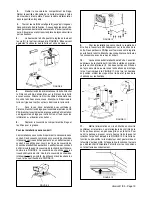
8.
Replace the field wiring compartment cover and the
grease filters
For ductless installations:
Ductless installations require a ductless kit. This kit consists
of alower chimney cover with holes for the exhaust air, a
ductless diverter, two grids to cover the holes in the chimney
cover, two charcoal filters. The ductless diverter must be
installed before the lower chimney cover is attached as in
FIGURE 9. The lower chimney cover without holes should
be discarded. Once the lower chimney cover with holes is
installed, the grids are inserted into the holes as illustrated
in FIGURE 10.
FIGURE 9
FIGURE 12
FIGURE 10
9.
For ducted installations, the damper must be attached
to the exhaust opening on the top of the canopy. Two small
phillips screws are provided with the damper to attach it to
the canopy. Connect the ductwork and seal all connections
with duct tape.
10.
The chimney must be attached to the body of the
rangehood. The upper section of the chimney (S) must be
installed first, then the lower section (I). Both sections are
secured to the wall under the mounting brackets as indicated in
FIGURE 11. Once the chimney is in the final position, screws
are used to secure the top and bottom of the chimney to the
brackets.
FIGURE 11
11.
Turn the power supply on. Turn on blower and light.
The rangehood controls are located in a gray panel on the
canopy's underside. To open the panel, press up on the
front edge and release as indicated in FIGURE 12. If the
rangehood does not operate, check that the circuit breaker
is not tripped or the house fuse blown. If the unit still does
not operate, disconnect the power supply and check that the
wiring connections have been made properly.
Содержание Nova
Страница 12: ...4324289...


