


18
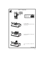
Installation of wiring connection
5HPRYHWKHFRYHUIURPWKH¿HOGZLULQJFRPSDUWPHQW
5HPRYHWKHZLULQJHOHFWULFDONQRFNRXWXVLQJDÀDW
blade screwdriver. Feed the Power Supply Cable
through the electrical knockout.
Connect the Power Supply Cable to the rangehood.
Attach the White lead of the power supply (
A
) to the
White lead of the rangehood (
D
) with a twist-on type
wire connector. Attach the Black lead of the power
supply to the Black lead of the rangehood (
B
) with
a twist-on type wire connector (
C
). Connect the
Green (
E
) (Green and Yellow) ground wire under
the Green grounding screw.
5HSODFH WKH ¿HOG ZLULQJ FRPSDUWPHQW FRYHU DQG
WKHJUHDVH¿OWHUV
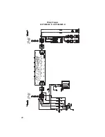
Hood wiring
USE AND CARE INFORMATION
G.
Indicator Light
L.
Lights - On and Off.
V1.
Low Speed.
V2.
Medium Speed.
V3.
Maximum Speed..
T1. Fan Off Button:Turn the blower Off. The fan can be oper-
ated by pressing any of the fan setting buttons.
Hold down this button for 2 seconds to activate delayed
off function which will keep the fan On for 15 minutes and
automatically shut Off.
T2. Fan Settings Buttons: Low Speed.
T3. Fan Settings Buttons: Medium Speed.
T4. Fan Settings Buttons: High Speed.
Hold down the button for 2 seconds to activate the INTEN-
SIVE SPEED, which is timed to run for 10 minutes. At the
end of this time it will automatically return to the speed set
before.Suitable to deal with maximum levels of cooking
fumes.
L. Light Button: On/Dim/Off switch for the halogen lights.
Press the LIGHT button to turn the light on, again to set
the lights to dimmer, and again to turn off.
L
T1
T2
T3
T4
L
V1
V2
V3
G
For Best Results
6WDUWWKHUDQJHKRRGVHYHUDOPLQXWHVEHIRUHFRRNLQJWRGHYHORSSURSHUDLUÀRZ$OORZWKHUDQJHKRRGWRRSHU
-
ate for several minutes after cooking is complete to clear all smoke and odors from the kitchen.
"DU@MSD(
"DU@MSD((
Содержание LEVA24SS300-B
Страница 5: ...5 RANGEHOOD DIMENSIONS Min 24 8 3...
Страница 14: ...14 Installation for Mounting on the Wall Installation for Mounting to the cabinet 15 17...
Страница 20: ...20 U Wiring Diagram LEVT30SS400 B LEVT36SS400 B...
Страница 26: ...26 DIMENSIONS DE LA HOTTE Min 24 8 3...
Страница 35: ...35 15 17 Installation pour montage mural Installation pour montage l armoire...
Страница 41: ...41 U Sch ma de c blage LEVT30SS400 B LEVT36SS400 B...
Страница 44: ...991 0379 950_03 160115...


