Faber DAMA ISOLA Series Скачать руководство пользователя страница 41

41

TODAS LAS ABERTURAS DE LA PARED Y EL PISO DONDE ESTÁ INSTALADA LA 

CAMPANA SE DEBEN SELLAR.

Esta campana requiere por lo menos 24 "de espacio libre entre el fondo de la campana y la 

superficie de cocción o encimera. Esta campana ha sido aprobada por UL a esta distancia del 

plano de cocción. 

Esta distancia mínima puede ser mayor dependiendo de los códigos de construcción locales. Para 

los planos de cocción de gas y las cocinas combinadas, se recomienda y puede ser necesario 

un mínimo de 30".

Los gabinetes de arriba a ambos lados de esta unidad deben estar a un mínimo de 18" por encima 

de la superficie de cocción o encimera. Consulte las instrucciones de instalación del plano de 

cocción o de la cocina dadas por el fabricante antes de realizar cualquier recorte. INSTALACIÓN 

EN CASA MÓVIL La instalación de esta campana debe cumplir con las Normas de Construcción 

y Seguridad de Viviendas Manufacturadas, Título 24 CFR, Parte 3280 (anteriormente Normal 

Federal para la Construcción y seguridad de las Viviendas Móviles, Título 24, HUD, parte 280). 

Vea Requisitos eléctricos.

• El sistema de ventilación DEBE terminar fuera del hogar.
• 

NO

 termine el conducto en un ático u otro espacio cerrado.

• 

NO(2) utilice tapas de pared tipo lavadero de 4".

• No se recomienda el uso de conductos flexibles.

• NO

 obstruya el flujo de aire de combustión y ventilación.

• El incumplimiento de los requisitos de ventilación puede provocar un incendio.

   ADVERTENCIA

!

REQUISITOS DE VENTILACIÓN

Determine qué método de ventilación es mejor para su aplicación. El conducto puede extenderse 

a través de la pared o el techo.

La longitud del conducto y el número de codos deben mantenerse al mínimo para proporcionar 

un rendimiento eficiente.  El tamaño del conducto debe ser uniforme.  No instale dos codos juntos.  

Use cinta adhesiva para sellar todas las juntas en el sistema de conductos.  Utilice calafateo para 

sellar la pared exterior o la abertura del piso alrededor de la tapa.

No se recomienda el uso de conductos flexibles. El conducto flexible crea una con

-

trapresión y una turbulencia del aire que reduce considerablemente el rendimiento.

Asegúrese de que haya suficiente espacio libre dentro de la pared o el piso para el conducto de 

escape antes de hacer recortes.  No corte una viga o un poste a menos que sea absolutamente 

necesario.  Si se debe cortar una viga o un poste, se debe construir una estructura de soporte. 

ADVERTENCIA - Para reducir el riesgo de incendio, use solamente conductos de metal.
PRECAUCIÓN - Para reducir el riesgo de incendio y para descargar adecuadamente el 

aire, asegúrese de sacar el aire - No expulse los humos en espacios dentro de paredes 

o techos, áticos, espacios angostos o garajes. 

3.  Al cortar o perforar la pared o el techo, no dañe el cableado eléctrico ni otros ser-

vicios ocultos.

4.  Los ventiladores con conductos siempre deben tener salida al exterior.

Содержание DAMA ISOLA Series

Страница 1: ...DAMAIS36SSV DAMAIS42SSV DAMA ISOLA Installation Instructions Use and Care Information Instructions d installation Utilisez et d entretien Instrucciones de instalaci n Informaci n de uso y cuidado...

Страница 2: ...with your back to an exit Based on Kitchen Firesafety Tips published by NFPA WARNING TO REDUCE THE RISK OF FIRE OR ELECTRIC SHOCK do not use this fan with any solid state speed control device WARNING...

Страница 3: ...DO NOT terminate the ductwork in an attic or other enclosed space DO NOT use 4 laundry type wall caps Flexible type ductwork is not recommended DO NOT obstruct the flow of combustion and ventilation a...

Страница 4: ...opper cable Allow some slack in the cable so the appliance can be moved if servicing is ever necessary A UL Listed 1 2 conduit connector must be provided at each end of the power supply cable at the a...

Страница 5: ...5 RANGEHOOD DIMENSIONS 0 1 0 Min 24 Min 30...

Страница 6: ...ded 6 Round Metal ductwork Components Ref Qty Product Components 1 1 HoodBody completewith Con trols Light Filters Blower 2 1 Telescopic Chimney comprising 2 1 1 Upper Section 2 2 1 Lower Section 7 1...

Страница 7: ...7 Choose your ducting method Non Ducted Recirculation Ducted Venting Installation Requires Ductless Accessory Kit purchased separately 6...

Страница 8: ...Supply Cable Use caulking to seal around the hole A knockout for threading through the Power Supply from the ceiling is located on the top of the frame Do not connect the Power Cable to the Wiring Box...

Страница 9: ...d to adjust the height of the frame proceed as follows Unfasten the metric screws joining the two columns located at the sides of the frame 1 2 3 4 5 6 Adjust the frame to the height required then ref...

Страница 10: ...TE The chimney structure can reduce down to a 27 minimum height To reduce the height the middle section of the support structure needs to be removed Out of the box the minimum chimney length is 32 Ins...

Страница 11: ...ough the strain relief Next position the chimney support so that the large end of the keyhole slots are over the ceiling attachment screws or bolts Then push the chimney support so that the bolts are...

Страница 12: ...t on type wire connector 1 The UPPER CHIMNEY COVER C in FIGURE 13 attaches to the top of th support structure using tw screwsprovided GinFIGURE 13 If using the High Ceilin ChimneyKit usetheUPPER CHIMN...

Страница 13: ...MNEY COVER D in FIGURE 12 and snap in the VENT GRIDS C in FIGURE 12 supply cable connectors are ground wire from home power supply een ground screw power supply cable power supply cable connected to g...

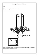
Страница 14: ...filters from the hood canopy Remove any activated charcoal filters Working from below fix the hood canopy to the frame where indicated using the 4 screws 12q then tighten all the screws securely Atta...

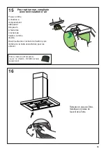
Страница 15: ...ce indicated with the lastic fixing cable component 11 as shown without stress the wiring grounding included Connect the connector of cable from the Hood Body to the Blower as shown Make the Internal...

Страница 16: ...filter in the correct position and block it by the fixing hooks as shown Unlock the fixing hooks towards the back of the insert hood to remove Reinstall the metal grease filters from the hood canopy...

Страница 17: ...off function which will keep the fan on for 15 minutes and automatically shut off T2 Fan settings buttons Low speed T3 Fan settings buttons Medium speed T4 Fan settings buttons High speed Intensive s...

Страница 18: ...d and must be replaced approximately every 4 months of operation or more frequently for particularly heavy usage Remove the Filters one at a time pushing them to wards the back of the unit and at the...

Страница 19: ...19 Wiring Diagram 991 0530 011 H90 503 D00004494_00 120V 60Hz...

Страница 20: ...om accident alteration misuse abuse fire flood acts of God improper installation installation not in accordance with electrical or plumbing codes or Faber documentation or use of products not approved...

Страница 21: ...e se trouve derri re vous pendant que vous teignez les flammes D apr s le guide Kitchen Firesafety Tips publi par la NFPA aux tats Unis AVERTISSEMENT POURR DUIRELERISQUED INCENDIEOUDECHOC LECTRIQUE n...

Страница 22: ...une meilleure efficacit la longueur des conduits et le nombre de coudes doivent tre le pluslimit squepossible Lediam tredesconduitsdevrait treuniforme N installezpasdeuxcoudes ensemble Utilisez un ru...

Страница 23: ...ermettre le d placement de l appareil si des travaux d entretien s av raient n cessaires Un raccord de conduit homologu par l UL de 1 2 doit tre install aux deux extr mit s du c ble d alimentation au...

Страница 24: ...24 DIMENSIONS DE LA HOTTE 0 1 0 Min 24 Min 30...

Страница 25: ...up rieur 7 1b 1 Ch ssisinf rieur 10 1 Registre 57 8 11 1 Plastique for C ble fixation R f Qt Composants d installation 12q 4 Vis1 8 x1 4 21 1 Gabaritdeper age Qt Documentation 1 Moded emploi Trousse d...

Страница 26: ...26 6 Choisissez la m thode de canalisation Exige la trousse d accessoires sans conduit achet e s par ment Recyclage sans canalisation Installation avec ventilation canalis e...

Страница 27: ...hotte sera install e et marquez la clairement sur le plafond l aide d un crayon Un gabarit 21 pour le montage du socle est fournidansl emballage Utilisezcemod lepour indiquer les trous qui serviront f...

Страница 28: ...4 5 6 R glez le ch ssis la hauteur requise puis remettezenplacetouteslesvisenlev escomme ci dessus D vissez les deux vis qui fixent la section inf rieure de la chemin e et d tachez la du ch ssis inf r...

Страница 29: ...ure de la chemin e peut r duire jusqu une hauteur minimale de 27 Pour r duire la hauteur la section m diane de la structure de support doit tre retir Hors de la bo te la longueur minimale de la chemin...

Страница 30: ...ur les vis ou boulons de fixation au plafond Poussez ensuite le socle de chemin e de fa on ce que les boulons s engagent dans lapartie troitedesencoches Serrezfermement les quatre vis ou boulons Lemon...

Страница 31: ...ow ground wire under the Green grounding screw Attach the White lead of the power supply to the White lead of the rangehood with a twist on type wire connector Attach the Black lead of the power suppl...

Страница 32: ...equire nversion onents are E 12 Do MPER M r ductless e LOWER VER B hould be placed by holes from ersionKit FIGURE UCTLESS over the the EASY UCTLESS ENSIONS into the FIGURE 12 DUCTLESS INSTALLATIONS De...

Страница 33: ...auvent de la hotte Retirez tout filtre charbon actif En passant par le dessous fixez l auvent de la hotte au ch ssis aux endroits indiqu s en utilisant les 4 vis 12q puis serrez fermement toutes les...

Страница 34: ...iques internes Fixez le c ble l espace indiqu par le composant en plastique 11 comme illustr sans contrainte le c blage mise la terre incluse Connectez le connecteur du c ble du corps du a hotte au ve...

Страница 35: ...et bloquez le l aide des crochets de fixation comme illustr D verrouillez les crochets de fixation vers l arri re de la hotte encastrable pour les enlever Remettez en place les filtres metalliques gra...

Страница 36: ...ivation retard e qui teindra automatiquement le ventilateur apr s 15 minutes de marche T2 Boutons de r glage du ventilateur vitesse r duite T3 Boutons de r glage du ventilateur vitesse moyenne T4 Bout...

Страница 37: ...avable et ne peut pas tre r g n r Il doit tre remplac environ tous les 4 mois d utilisation ou plussouventencasd utilisationparticuli rementintensive Retirez les filtres un un en les poussant vers l a...

Страница 38: ...38 991 0530 011 H90 503 D00004494_00 Sch ma de c blage 120V 60Hz...

Страница 39: ...es d coulant d un accident d une modification de l utilisation incorrecte ou abusive d un incendie d une inondation d un cas de force majeure d une installation inad quate d une installation non confo...

Страница 40: ...cia una salida Basado en Consejos para luchas contra los incendios en las cocinas publicado por NFPA ADVERTENCIA PARAREDUCIRELRIESGODEDESCARGASEL CTRICASOINCEN DIOS nouseesteventiladorconning ndisposi...

Страница 41: ...mbusti n y ventilaci n El incumplimiento de los requisitos de ventilaci n puede provocar un incendio ADVERTENCIA REQUISITOS DE VENTILACI N Determinequ m tododeventilaci nesmejorparasuaplicaci n Elcond...

Страница 42: ...de tensi n en el cable para poder mover el dispositivo si alguna vez lo ne cesita Debe haber un conector de conducto de 1 2 homologado por UL en cada extremo del cable de suministro de energ a en el e...

Страница 43: ...43 0 1 0 Min 24 Min 30 DIMENSIONES DE LA CAMPANA...

Страница 44: ...nductomet licoredondode6 Componentes Ref Cdad Componentes del producto 1 1 Cuerpodelacampana completode Controles Luces Filtros Ventilador 2 1 Chimenea telesc pica que comprende 2 1 1 Secci n superior...

Страница 45: ...45 Requiere compra de accesorio de carb n activado 6 Elija su m todo de conducci n Sin conductos Opci n de recirculaci n Instalaci n de opciones de ventilaci n con conductos...

Страница 46: ...deenerg a Use masilla para sellar alrededor del agujero Un punto de salida para pasar cables a trav s de la fuente de alimentaci n desde el techo se encuentra en la parte superior del bastidor No cone...

Страница 47: ...stidor inferior Si necesita ajustar la altura del bastidor proceda de la siguiente manera Afloje los tornillos m tricos que unen las dos columnas ubicadas a los lados del bastidor 1 2 3 4 5 6 Ajusteel...

Страница 48: ...la chimenea puede reducir hasta una altura m nima de 27 Para reducir la altura la secci n central de la estructura de soporte necesita ser retirada Fuera de la caja la longitud m nima de la chimenea...

Страница 49: ...itracci n A continuaci n coloque el soporte de la chimenea de forma que el extremo grande de lasranurasperforadasquedesobrelostornillos o pernos de fijaci n al techo A continuaci n empuje el soporte d...

Страница 50: ...uctless installations require a Ductless Conversion Kit whose components are pictured in FIGURE 12 Do not use the DAMPER M in FIGURE 1 for ductless installations The LOWER CHIMNEY COVER B in FIGURE 1...

Страница 51: ...ed to green FIGURE 11 ns require nversion onents are E 12 Do MPER M r ductless e LOWER VER B hould be placed by holes from ersionKit FIGURE UCTLESS over the the EASY UCTLESS ENSIONS into the FIGURE 12...

Страница 52: ...de la campana Retire cualquier filtro de carb n activado Trabajando desde abajo fije la capota de la campana al bastidor donde se indica usando los 4 tornillos 12q luego apriete todos los tornillos co...

Страница 53: ...io indicado con cable de fijaci n del componente 11 como se muestra sin tensar el cableado incluyendo la conexi n de tierra Conecte el conector del cable del cuerpo de la campana al ventilador como se...

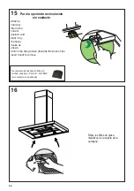
Страница 54: ...oks as shown Unlock the fixing hooks towards the back of the insert hood to remove 16 Para la opci n de recirculaci n sin conducto Retire los filtros de grasa metallicos de la capota de la campana Se...

Страница 55: ...antendr el ventilador encendido durante 15 minutos y se apagar autom ticam ente T2 Botones de ajuste del ventilador velocidad baja T3 Botones de ajuste del ventilador velocidad media T4 Botones de aju...

Страница 56: ...ado y debe ser reemplazado aproximadamente cada 4 meses de operaci n o m s frecuentemente con uso intensivo Retire los filtros de a uno por vez empuj ndolos hacia la parte posterior de la unidad y al...

Страница 57: ...57 Diagrama de cableado 991 0530 011 H90 503 D00004494_00 120V 60Hz...

Страница 58: ...r est n garantizados contra cualquier defecto de materiales o mano de obra para el comprador original por un per odo de 1 a o a partir de la fecha de compra original requiere prueba de compra Esta gar...

Страница 59: ...59...

Страница 60: ...991 0568 764_01 181121 D00005441_00...

Отзывы: