background image

31

Remarque : La hotte doit être installée sur un circuit électrique séparé.

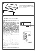
• Une mise à la terre électrique est requise pour cette hotte.
• N'UTILISEZ PAS un tuyau d'eau froide pour la mise à la terre si celui-ci est branché par des 

joints en plastique, par des rondelles non métalliques ou d'autres matériaux.

• N'UTILISEZ PAS une conduite de gaz pour la mise à la terre.
• N'INSTALLEZ PAS un fusible sur le circuit neutre ou le circuit de mise à la terre.  La présence 

d'un fusible dans le circuit neutre ou de mise à la terre peut entraîner un choc électrique.

• Consultez un électricien qualifié si vous n'êtes pas certain de la mise à la terre de la hotte. 
• Le non-respect des exigences de la fiche technique électrique pourrait entraîner un incendie.   

   AVERTISSEMENT

!

Avertissement de la proposition 65 de l'État de Californie (US seulement)

 ATTENTION

Ce produit contient des produ

its chimiques connus de l'État de Californie pour causer le

cancer et des malformations congénitales ou d'autres problèmes de reproduction.

Pour plus d'informations, visitez www.P65Warnings.ca.gov

Содержание Camino Pro CAPR36SS600

Страница 1: ...llation Instructions Use and Care Information Instructions d installation Utilisez et d entretien Instrucciones de instalaci n Informaci n de uso y cuidado CAMINO PRO CAPR36SS600 CAPR36SS1200 CAPR48SS...

Страница 2: ...with your back to an exit Based on Kitchen Firesafety Tips published by NFPA WARNING TO REDUCE THE RISK OF FIRE OR ELECTRIC SHOCK do not use this fan with any solid state speed control device WARNING...

Страница 3: ...he flow of combustion and ventilation air Failure to follow venting requirements may result in a fire WARNING VENTING REQUIREMENTS Determine which venting method is best for your application Ductwork...

Страница 4: ...in electrical shock Check with a qualified electrician if you are in doubt as to whether the rangehood is properly grounded Failure to follow electrical requirements may result in a fire WARNING State...

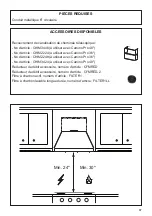
Страница 5: ...5 1 MOTOR RANGEHOOD DIMENSIONS 36 DRAFT 28 NOV 2018 17 1 MOTOR RANGEHOOD REAR VENTING...

Страница 6: ...6 2 MOTOR RANGEHOOD DIMENSIONS 36 9 13 16 11 7 16 11 1 16 4 15 16 10 DUCT TRANSITION FOR 2 MOTOR RANGEHOOD 36 DRAFT 28 NOV 2018 15 53...

Страница 7: ...7 2 MOTOR RANGEHOOD DIMENSIONS 48 DRAFT 28 NOV 2018 16 20 9 13 16 11 7 16 11 1 16 4 15 16 10 DUCT TRANSITION FOR 2 MOTOR RANGEHOOD 48...

Страница 8: ...mounting Qty Documentation 1 Instruction Manual MAIN PARTS 2 MOTOR RANGEHOOD 36 Components Ref Qty Product Components 1 1 Hood Body complete with Controls Light 2 1 Duct transition 6 3 Grease filters...

Страница 9: ...9 1 Recirculation Vent Grill 10 2 Damper 5 7 8 11 2 Blower Ref Qty Installation Components 12a 2 Wall plug 12b 4 Screws 3 16 x1 15 16 12c 8 Grease filters screws 5 32 x5 16 12d 4 screws 1 8 x1 4 12e...

Страница 10: ...ith 48 Camino Pro sku CHIM2224 Use with 36 Camino Pro sku CHIM2248 Use with 36 Camino Pro sku CHIM3424 Use with 48 Camino Pro CFM Reducer Accessory Kit sku CFMRED CFM Reducer Accessory Kit sku CFMRED...

Страница 11: ...e the screws are removed extract it from the body of the Hood and position it so the transition opening is facing to the rear wall from the back remove and rotate 180 degrees to the left and then flip...

Страница 12: ...12 Install the motor into the upper of the hood using the 2 screws 12e supplied Put the motor in the hood body 2 3 4 9 hole end Connect the wire cable 9 hole end to the motor 180 90...

Страница 13: ...OR RANGEHOOD TOP DUCTED INSTALLATION 1 2 Install the motor into the rear of the hood using the 2 screws 12e supplied Put the motor in the hood body 3 9 hole end Connect the wire cable 9 hole end to th...

Страница 14: ...RE 19 wiring and test FIGURE 20 ATION WITH IB1200 INTERNAL BLOWER 1200 cfm he Plate B FIGURE 14 which came with the internal on top of the rangehood with the holes located closer to Use 9 screws suppl...

Страница 15: ...RUCTIONS Installation Instruction for Mounting on the Wall Draw a vertical line on the supporting wall as high as practical at the center of the area in which the hood will be installed Draw a horizon...

Страница 16: ...t L distance on the left and right of vertical line The distance L changes for all dimension of Hood Insert the two wall plugs 12a in the holes as shown and fix them Installation for 1 Motor Rangehood...

Страница 17: ...ntal line and at L distance on the left and right of vertical line The distance L changes for all dimension of Hood Insert the two wall plugs 12a in the holes as shown and fix them For a different typ...

Страница 18: ...cture Mark the wall where indicated Drilldirectlyinto 5 16 holesatallthecenterpointsmarked Insert the purchased wall plugs in the holes Using thhe remaining screws to anchor the hood in holes If insta...

Страница 19: ...HODS 6 Install Roof or Wall Cap purchased separately Connect the 6 metal ductwork to the Roof or Wall Cap and then attach ductwork 1 AND 2 MOTORS STANDARD DUCTING METHODS Vertical Horizontal Rear Vali...

Страница 20: ...TORS DUCTING METHODS 10 Install Roof or Wall Cap purchased separately Connect the 10 metal ductwork to the Roof or Wall Cap and then attach ductwork Fix the Duct transition in the hood body with 4 scr...

Страница 21: ...ucted Recirculation venting route the ductwork to a location above the hood where the discharge is vented back into the room Use the included Recirculation Vent Grill 9 to cover the opening Secure the...

Страница 22: ...to each end of the blower Each charcoal filter attaches to the grid on the side of the blower Rotate the filter clockwise to install and counterclockwise to remove FIGURE 3C Replace all grease filters...

Страница 23: ...ire connector Attach the Black lead of the power supply to the Black lead of the rangehood B with a twist on type wire connector C Connect the Green E Green and Yellow ground wire under the Green grou...

Страница 24: ...crews 12c Use two hands to insert and remove the filters The 36 hood has 3 Filters The 48 hood has 4 Filters 9e 7 6 9e 7 INSTALLATION CONTINUED Optional Telescopic Chimney Extension Installation Refer...

Страница 25: ...rn the motor off Alternatively a quick turn of the knob to the left backwards thru the speeds 1 turn to the left past speed 1 turns the motor off B0 No Color Delay auto shut off Hold the knob to the r...

Страница 26: ...hood Toinstallthefilters usethetwoknobstoholdthefilter and insert the filter into the front edge of the hood withtheknobsfacingoutintothespringloadedslot Installtheotherendofthefilterabovethegreaserai...

Страница 27: ...from the drawing or bring modifications without the prior written conset of franke Techology and Trademark Doc status Approved date Modification description Approved by WIRING DIAGRAM M8 4V ATF SENSOR...

Страница 28: ...om accident alteration misuse abuse fire flood acts of God improper installation installation not in accordance with electrical or plumbing codes or Faber documentation or use of products not approved...

Страница 29: ...nevoiedesortiesetrouvederri revouspendantquevous teignezlesflammes D apr sleguide KitchenFiresafetyTips publi parlaNFPAaux tats Unis AVERTISSEMENT POURR DUIRELERISQUED INCENDIEOUDECHOC LECTRIQUE n uti...

Страница 30: ...mble Utilisezunrubanpourcanalisationsafindescellertouslesjointsdusyst medeconduits Utilisezuncalfeu tragepourscellerlesouverturesdanslemurext rieurouleplancher autourduclapet Iln estpasrecommand d uti...

Страница 31: ...mise la terre La pr sence d un fusible dans le circuit neutre ou de mise la terre peut entra ner un choc lectrique Consultez un lectricien qualifi si vous n tes pas certain de la mise la terre de la...

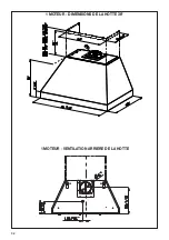
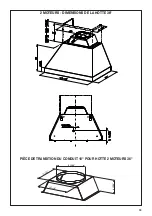
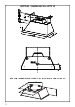
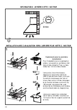
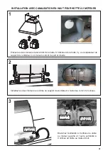
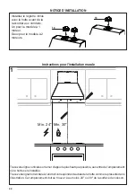
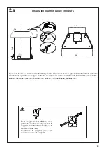
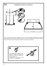
Страница 32: ...32 1 MOTEUR DIMENSIONS DE LA HOTTE 36 DRAFT 28 NOV 2018 17 1 MOTEUR VENTILATION ARRI RE DE LA HOTTE...

Страница 33: ...33 2 MOTEURS DIMENSIONS DE LA HOTTE 36 9 13 16 11 7 16 11 1 16 4 15 16 PI CE DE TRANSITION DU CONDUIT 10 POUR HOTTE 2 MOTEURS 36 DRAFT 28 NOV 2018 15 53...

Страница 34: ...34 2 MOTEURS DIMENSIONS DE LA HOTTE 48 DRAFT 28 NOV 2018 16 20 9 13 16 11 7 16 11 1 16 4 15 16 PI CE DE TRANSITION DU CONDUIT 10 POUR HOTTE 2 MOTEURS 48...

Страница 35: ...isse 3 16 x3 8 12e 2 Vis de fixation de moteur 3 16 x 3 8 12f 2 Vis 1 8 x 3 8 pour le montage de la grille d vent de recyclage Qt Documentation 1 Mode d emploi Composants R f Qt Composants du produit...

Страница 36: ...rage 2 1 Pi ce de transition du conduit 6 4 Filtres graisse 7 8 Boutons de filtre 8 1 Goutti re 9 1 Grille d vent de recyclage 10 2 Registres 5 7 8 11 2 Ventilateurs R f Qt Composants d installation 1...

Страница 37: ...d article CHIM2224 utiliser avec Camino Pro 36 No d article CHIM2248 utiliser avec Camino Pro 36 No d article CHIM3424 utiliser avec Camino Pro 48 R ducteur de d bit accessoire num ro d article CFMRE...

Страница 38: ...z le support du b ti de la hotte et placez le de fa on ce que l ouverture de passage de l air se trouve face au mur arri re d gagez le de l arri re et faites le tourner de 180 degr s vers la gauche pu...

Страница 39: ...Extr mit 9 orifices 180 90 Installez le moteur dans la partie sup rieure de la hotte l aide des 2 vis 12e fournies Placez le moteur dans le b ti de la hotte Branchez l extr mit 9 orifices du c ble au...

Страница 40: ...ISATION EN HAUT POUR HOTTE 1 MOTEUR 1 2 Installez le moteur l arri re de la hotte l aide des 2 vis 12e fournies Placez le moteur dans le b ti de la hotte 3 Branchez l extr mit 9 orifices du c ble au m...

Страница 41: ...d Install the 4 side trim he outside of the hood using 16 part 9b screws see il installation in FIGURE 15 FIGURE 17 FIGURE 18 6 Install the 2 dampers on top of the hood If you want one 10 round duct t...

Страница 42: ...NSTALLATION Instructions pour l installation murale Tracezuneligneverticalesurlemurd appuileplushautquepossible aucentredel emplacement o la hotte sera install e Tracez une ligne horizontale l endroit...

Страница 43: ...L droite et gauche de la ligne verticale La distance L varie en fonction de la dimension de la hotte Ins rez les deux chevilles 12a dans les orifices comme illustr et fixez les Installation pour hott...

Страница 44: ...ntale et la distance L droite et gauche de la ligne verticale La distance L varie en fonction de la dimension de la hotte Ins rez les deux chevilles 12a dans les orifices comme illustr et fixez les Po...

Страница 45: ...ep re sur le mur l endroit indiqu Percez des trous de 5 16 po directement au centre des rep res Ins rez les chevilles achet es dans les trous Utilisez les deux vis restantes pour ancrer la hotte aux t...

Страница 46: ...toiture ou le clapet mural achet s par ment Raccordez le conduit m tallique de 6 au clapet de toiture ou au clapet mural puis raccordez les conduits M THODES DE CANALISATION STANDARD POUR HOTTES 1 ET...

Страница 47: ...Installez le clapet de toiture ou le clapet mural achet s par ment Raccordez le conduit m tallique de 10 au clapet de toiture ou au clapet mural puis raccordez les conduits Fixez la pi ce de transitio...

Страница 48: ...sans canalisation dirigez les conduits un emplace ment au dessus de la hotte o l air vacu est retourn dans la pi ce Utilisez la grille d vent de recyclage incluse 9 pour couvrir l ouverture Fixez la g...

Страница 49: ...que extr mit du ventilateur Chaque filtre charbon se fixe une grille sur le c t du ventila teur Faites tourner le filtre dans le sens des aiguilles d une montre pour l installer et dans le sens contra...

Страница 50: ...au fil noir de la hotte B l aide d un connecteur verrouill par rotation C Branchez le fil vert vert et jaune E de mise la terre sous la vis de mise la terre verte Remettez le couvercle du compartiment...

Страница 51: ...mains pour ins rer et retirer les filtres La hotte 36 a 3 filtres La hotte 48 a 4 filtres 9e 7 6 9e 7 INSTALLATION SUITE Installation du prolongement de chemin e t lescopique en option Reportez vous a...

Страница 52: ...indre le moteur Un tour rapide du bouton vers la gauche diminue la vitesse progressivement 1 tour gauche diminue la vitesse d un cran jusqu teindre le moteur B0 Sans couleur Retarder l extinction auto...

Страница 53: ...le filtre l aide des deuxboutonsetins rez ledanslebordavantdelahotte en orientant les boutons vers l ext rieur dans la fente ressort Installez l autre extr mit du filtre au dessus de la goutti re l a...

Страница 54: ...the drawing or bring modifications without the prior written conset of franke Techology and Trademark Doc status Approved date Modification description Approved by WIRING DIAGRAM M8 4V ATF SENSOR GU1...

Страница 55: ...es d coulant d un accident d une modification de l utilisation incorrecte ou abusive d un incendie d une inondation d un cas de force majeure d une installation inad quate d une installation non confo...

Страница 56: ...VERTENCIA PARAREDUCIRELRIESGODEDESCARGAEL CTRICAOINCENDIO nouse este ventilador con ning n dispositivo de control de velocidad de estado ADVERTENCIA PARA REDUCIR EL RIESGO DE INCENDIOS DESCARGAS EL CT...

Страница 57: ...os ticos espacios angostos o garajes TODAS LAS ABERTURAS DE LA PARED Y EL PISO DONDE EST INSTALADA LA CAMPA NA SE DEBEN SELLAR Esta campana requiere al menos 24 de espacio libreentre la parte inferior...

Страница 58: ...ga el ctrica Consulte con un electricista calificado si tiene dudas acerca de si la campana est correctamente conectada a tierra El incumplimiento de los requisitos el ctricos puede provocar un incend...

Страница 59: ...59 DRAFT 28 NOV 2018 17 DIMENSIONES DE LA CAMPANA DE 1 MOTOR DE 36 CAMPANA DE 1 MOTOR DE VENTILACI N TRASERA...

Страница 60: ...60 9 13 16 11 7 16 11 1 16 4 15 16 DRAFT 28 NOV 2018 15 53 DIMENSIONES DE LA CAMPANA DE 2 MOTORES DE 36 TRANSICI N DEL CONDUCTO DE 10 PARA CAMPANA DE 2 MOTORES DE 36...

Страница 61: ...61 DRAFT 28 NOV 2018 16 20 9 13 16 11 7 16 11 1 16 4 15 16 DIMENSIONES DE LA CAMPANA DE 2 MOTORES DE 48 TRANSICI N DEL CONDUCTO DE 10 PARA CAMPANA DE 2 MOTORES DE 48...

Страница 62: ...6 x 3 8 12f 2 Tornillos 1 8 x 3 8 para el montaje de la rejilla de ventilaci n Cdad Documentaci n 1 Manual de instrucciones PIEZAS PRINCIPALES DE LA CAMPANA DE 2 MOTOR DE 36 Componentes Ref Cdad Compo...

Страница 63: ...tros de grasa 7 8 Perillas del filtro 8 1 Engrasador 9 1 Rejilla de ventilaci n de recirculaci n 10 2 Registro 5 7 8 11 2 Ventilador Ref Cdad Componentes del Instalaci n 12a 2 Taco para pared 12b 4 To...

Страница 64: ...CHIM3448 Usar con Camino Pro de 48 sku CHIM2224 Usar con Camino Pro de 36 sku CHIM2248 Usar con Camino Pro de 36 sku CHIM3424 Usar con Camino Pro de 48 Kit de accesorio reductor CFM sku CFMRED Kit de...

Страница 65: ...a y col quelo de modo que la abertura de transici n quede orientada hacia la pared posterior desde la parte posterior g relo 180 grados hacia la izquierda y g relo hacia atr s 90 grados como se muestr...

Страница 66: ...90 Instale el motor en la parte superior de la campana con los 2 tornillos 12e suministrados Coloque el motor en el cuerpo de la campana Conecte el extremo de 9 orificios del cable al motor Extremo d...

Страница 67: ...ACI N DE LA CAMPANA DE 1 MOTOR SUPERIOR DE CONDUCTO Instale el motor en la parte trasera de la campana con los 2 tornillos 12e suministrados Coloque el motor en el cuerpo de la campana Conecte el extr...

Страница 68: ...ll the 4 side trim he outside of the hood using 16 part 9b screws see il installation in FIGURE 15 FIGURE 17 FIGURE 18 6 Install the 2 dampers on top of the hood If you want one 10 round duct to come...

Страница 69: ...ores INSTRUCCIONES DE INSTALACI N Instrucciones de instalaci n para el montaje en la pared Dibuje una l nea vertical en la pared de soporte tan alto como sea posible en el centro del rea donde se inst...

Страница 70: ...a L a la izquierda y derecha de la l nea vertical La distancia L cambia para todas las dimensiones de campanas Inserte los dos tacos 12a en los agujeros como se muestra y f jelos Instalaci n para la c...

Страница 71: ...tal y a la distancia L a la izquierda y derecha de la l nea vertical La distancia L cambia para todas las dimensiones de campanas Inserte los dos tacos 12a en los agujeros como se muestra y f jelos Pa...

Страница 72: ...tes para anclar la campana en los agujeros 11b 3 4 5 Enganche el cuerpo de la campana en los tacos 12a Use un nivel para asegurarse de que el soporte de fijaci n est nivelado ajustando los tornillos c...

Страница 73: ...CONDUCTOS EST NDAR PARA 1 O 2 MOTORES Vertical Horizontal M TODOS DE COLOCACI N DE CONDUCTOS PARA 1 O 2 MOTORES DE 6 Instale el techo o la tapa de pared comprados por separado Conecte los conductos me...

Страница 74: ...TORES DE 10 Instale el techo o la tapa de pared comprados por separado Conecte los conductos met licos de 10 al techo o a la tapa de pared y luego conecte los conductos Fije la transici n del conducto...

Страница 75: ...circulaci n incluida 9 para cubrir la abertura Fije la rejilla con los 2 tornillos 12f provistos en el kit de instalaci n Si no se utiliza la rejilla direccional coloque un tubo recto de al menos 15 d...

Страница 76: ...opla dor Cada filtro de carb n se conecta a la rejilla en el costado del ventilador Gire el filtro en el sentido horario para instalarlo y en sentido antihorario para extraerlo FIGURA 3C Reemplace tod...

Страница 77: ...n Conecte el cable negro de la fuente de alimentaci nalcablenegrodelacampana B con un conector de cable tipo twist on C Conecte el cable de tierra verde E verde y amarillo debajo del tornillo de conex...

Страница 78: ...para insertar y retirar los filtros La campana de 36 tiene 3 filtros La campana de 48 tiene 4 filtros 9e 7 6 9e 7 12c 12c 1 2 INSTALACI N CONTINUADA Instalaci n opcional de la extensi n de la chimenea...

Страница 79: ...o giro de la perilla hacia la izquierda hacia atr s a trav s de las velocidades 1 giro hacia la izquierda pasada la velocidad 1 apaga el motor B0 Sin color Apagado autom tico con retardo Mantenga la p...

Страница 80: ...den regenerar y deben reemplazarse aproximadamente cada 4 meses de operaci n o con mayor frecuencia con un uso intensivo Retire el filtro de carb n gir ndolo en el sentido de las agujas del reloj haci...

Страница 81: ...om the drawing or bring modifications without the prior written conset of franke Techology and Trademark Doc status Approved date Modification description Approved by WIRING DIAGRAM M8 4V ATF SENSOR G...

Страница 82: ...r est n garantizados contra cualquier defecto de materiales o mano de obra para el comprador original por un per odo de 1 a o a partir de la fecha de compra original requiere prueba de compra Esta gar...

Страница 83: ...83...

Страница 84: ...991 0572 967_03 190702 D00005715_02...

Отзывы: