


8
2
5 6
3 4
2
1
6
5 6
3 4
2
1
6
1
2
3
4
5
6
12
5/8
”
4
9/16
”
´
>
´
24”
24”
4
9/16
”
7.2.1
2.1
2.1
1
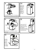
Draw a vertical line on the supporting wall as high as practical, at the center of the area in which
the hood will be installed.
Draw a horizontal line at where the bottom edge of the hood will be located as indicated in the figure
that is a minimum of 24" above cooking surface.
Draw a horizontal line where indicated above the cooking surface.
Place a bracket 7.2.1 on the wall as shown about 1
1/8
" from the ceiling or upper limit, aligning the
center (notch) with the vertical reference line and mark the wall at the centers of the holes in the bracket.
Place the second bracket 7.2.1 on the wall as shown, below the first bracket, at the height of the
upper chimney section supplied and aligning the center (notch) with the vertical line.
Mark the wall at the centers of the holes in the bracket and mark the point 1 and 2 for the Hood Body
installation as shown(12
5/8
" from the horizontal line and 4
9/16
" from the vertical line).
Drill ø 5/16" holes at all the center points marked (point 1,2,3,4,5,6) as shown.
Содержание BELA30SS600-B
Страница 5: ...5 RANGEHOOD DIMENSIONS Min 24...
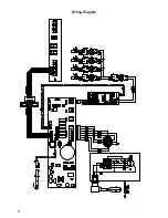
Страница 16: ...16 Wiring Diagram...
Страница 21: ...21 Min 24 DIMENSIONS DE LA HOTTE...
Страница 32: ...32 Sch ma de c blage...
Страница 34: ...34...
Страница 35: ...35...
Страница 36: ...991 0454 810_02 160504 D002767_01...