

Version 07/11 - Page 7
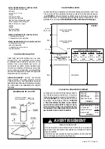
FIGURE 9
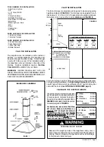
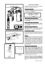
6.
Connect the Power Supply Cable to the rangehood. At-
tach the White lead of the power supply to the White lead of
the rangehood with a twist-on type wire connector. Attach
the Black lead of the power supply to the Black lead of the
rangehood with a twist-on type wire connector. Connect
the Green (Green and Yellow) ground wire under the Green
grounding screw.
7.
Replace the field wiring compartment cover and the grease
filters
8.
For ducted installations, the damper must be attached to
the exhaust opening on the top of the canopy. Connect the
ductwork and seal all connections with duct tape.
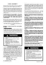
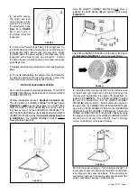
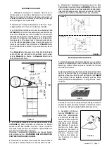
FOR DUCTLESS INSTALLATIONS
Do not use the damper for ductless installations. The UPPER
CHIMNEY COVER must be installed first, before the LOWER
CHIMNEY DUCTLESS.
Ductless installations require a
Ductless Conversion Kit
.
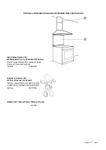
This kit consists of a LOWER CHIMNEY DUCTLESS
(A in
FIGURE 10)
with holes for the exhaust air, a DUCTLESS
DIVERTER
(C)
, two VENT GRIDS
(B)
to cover the holes in
the chimney cover, and two CHARCOAL FILTERS
(D)
. The
DUCTLESS DIVERTER must be installed before the LOWER
CHIMNEY DUCTLESS is attached
(as indicated by the arrow
in FIGURE 10)
. The LOWER CHIMNEY COVER without
holes should be discarded.
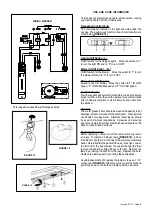
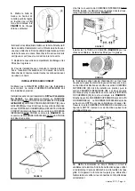
Once the LOWER CHIMNEY DUCTLESS with holes is
installed, the VENT GRIDS
(B)
are inserted into the holes
(FIGURE 11)
.
Attach the CHARCOAL FILTERS to both sides of the blower
(as indicated in FIGURE 12)
. Install the grease filters.
FIGURE 10
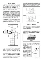
5.
Level the canopy.
The height and level
of the canopy can be
adjusted by rotating
the adjustment screws
(Item R in FIGURE
9)
on each side of
the blower inside the
rangehood
FIGURE 11
FIGURE 12
9.
Install the black chimney clips (
K
) into the holes located
on the left and right of the duct on the top of the body. The
chimney must be attached to the body of the rangehood, as
indicated in
FIGURE 13
. The UPPER CHIMNEY COVER
(C)
must be installed first, then the LOWER CHIMNEY
COVER
(B)
wraps around it. Both sections are secured to
the wall under the CHIMNEY MOUNTING BRACKETS
(H)
.
Secure the UPPER CHIMNEY COVER to the MOUNTING
BRACKETS with the CHIMNEY SCREWS
(J)
. Secure the
LOWER CHIMNEY COVER to the CANOPY
(A)
by inserting
the flanges at the bottom of the LOWER CHIMNEY COVER
into the slots on the top of the CANOPY. Insert 2 chimney
screws at the bottom of the lower Chimney.
10.
Turn the power supply on. Turn on blower and light. If
the rangehood does not operate, check that the circuit breaker
is not tripped or the house fuse blown. If the unit still does
not operate, disconnect the power supply and check that the
wiring connections have been made properly.
FIGURE 13
K


