3.5 STEERING STOP ADJUSTMENT
The steering stop adjustment is made at the factory.
There should be no need to alter it, unless a major com-
ponent such as the axle housing or spindle yoke has
been replaced for some reason.
The turn angle is set at 35°, and this can be checked with
a carpenter's power saw protractor on the wheel's inside
rim and a T-square laid along the frame rail with the vehi-
cle's steering at full lock. If an adjustment is necessary,
loosen the steering stop 12-point adjusting screw on the
rear of the spindle yoke and add or remove washers to
achieve desired turn angle. Torque the jam nut to
75 lb.-ft. The toe-in adjustment (Section 3.4) should be
completed before performing this procedure.
WARNING: THE POWER STEERING GEAR'S PRES-
SURE RELIEF SHOULD OCCUR AT
LEAST 1/8" BEFORE THE AXLE STEER-
ING STOPS ARE CONTACTED. IF THE
POWER STEERING PRESSURE RELIEF
NEEDS ADJUSTMENT CONSULT THE
VEHICLE MANUFACTURER BEFORE
OPERATING THE VEHICLE.
FAILURE
TO COMPLY CAN RESULT IN DAMAGE
TO THE STEERABLE DRIVE AXLE AND
OTHER STEERING COMPONENTS.
3.6 CAMBER ADJUSTMENT
Camber is set at the factory and is integral to the manu-
facture of the housing and steerable end components. It
cannot be changed.
3.7 CASTER ADJUSTMENT
Caster is specified by the vehicle manufacturer and can
be adjusted only by means of shims between the axle
spring seat and the spring. Changing the caster will
change the pinion angle and may affect the operation of
the front drive shaft.
3.8 BRAKE ADJUSTMENT
After an initial setup procedure, brake adjustment is
made automatically by the slack adjusters, and should
require no attention between relines. To adjust the slack
after a brake reline:
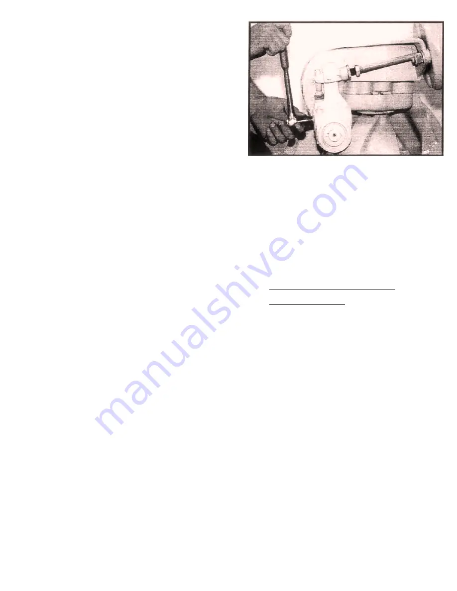
1. Using a 7/16 socket, rotate the hex extension on
the front of the slack adjuster clockwise until the
shoes first contact the drum. See
Figure 7.
Ro-
tate the hex extension 1/2 turn counterclock-
wise to back off the shoes and provide initial
running clearance.
A ratcheting noise while
backing off is normal.
2. Confirm that the drum rotates freely. Scraping
noises are OK, but no heavy drag should exist.
If excessive friction is present, continue to back
off the hex extension in 1/8 turn increments until
free motion is restored.
NOTE: It is preferable to have a slightly loose
initial setting than one that is too tight.
The adjuster will remove extra slack,
but cannot add any.
4.0 STEERABLE DRIVE END
DISASSEMBLY
4.1 GENERAL PRECAUTIONS FOR
DISASSEMBLY
CAUTION:
READ THIS SECTION BEFORE START-
ING THE DISASSEMBLY PROCEDURES.
1. Follow each procedure closely in each section,
making use of both text and figures.
2. The outside of the unit should be carefully
cleaned before starting disassembly. If steam
cleaning, ensure that breather and air fittings
are covered to prevent moisture from entering
the assembly.
3. Prepare a clean place to work. It is important
that no dirt or foreign material be allowed to en-
ter the unit during repairs.
4. Refer to the exploded views located in the parts
section as an aid in disassembly.
5. When disassembling the various assemblies,
lay all parts on a clean bench in the same se-
quence as removed. This procedure will sim-
plify reassembly and reduce the possibility of
losing parts.
– 11 –
1/96
Figure #7
Содержание SDA-2300
Страница 23: ... 22 06x45 r t I 01 50 t 449 I 07 375 03x45 030R MATERIAL STEEL 9 I WHEEL END INNER SEAL DR IVER 350 884 ...
Страница 25: ... 24 50 4 00 06x45 3 50 01 50 t KNURL MATERIAL STEEL 9 3 LOWER KINGPIN SEAL DRIVER 350 916 ...
Страница 26: ... 25 50 i 5 00 i j 06x45 03 38 KNURL MATERIAL STEEL 9 4 LOWER KINGPIN BEARING DRIVER 350 918 ...
Страница 29: ... 28 04 50 01 50 t r 06x45si 38 MATERIAL STEEL 9 7 INNER AXLE SEAL DRIVER 350 917 ...
Страница 31: ... 30 03x45 TYP 030R I 4 32 i 1 25 02 38 2 I 865 I B60 0 I 485 MATERIAL STEEL 9 9 CAMSHAFT SEAL DRIVER 350 846 ...


