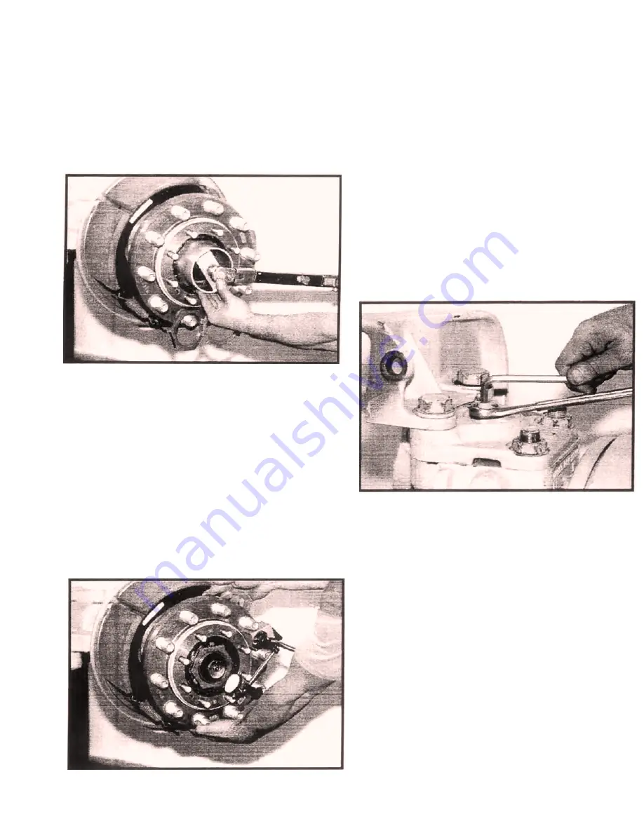
5. Remove the wheel bearing locknut and washer
from the spindle and loosen the bearing adjust-
ing nut.
6. Torque the bearing adjusting nut to 50 lb.-ft.
while simultaneously rotating the hub assem-
bly. (See Section Special Tools 9.16.) Loosen
the nut and repeat this procedure 2-3 times to
ensure that the bearings are seated properly.
After the final tightening, back off the nut 1/4
turn. See
Figure 2.
7. Install the wheel bearing lock washer and wheel
bearing adjustment nut, then torque locknut to
400 lb.-ft. (See Section Special Tools 9.16.)
Next, one tab on the lockwasher should be bent
inward and one bent outward across the flattest
part of the nut.
NOTE: With the outer locknut torqued to
specifications the wheel hub should
rotate freely
8. The wheel bearing end play should be checked
with a dial indicator as part of the adjustment
procedure. See
Figure 3
. The correct end play
setting is no less than .002" and no more than
.004".
9. Reinstall the drive flange over the hub assem-
bly. Then torque the drive flange locknuts to
175 lb.- ft.
3.3 KINGPIN ADJUSTMENT
1. The front of the vehicle should be raised, prop-
erly supported, and the front wheels removed
from the axle.
2. Loosen the lower kingpin locknut (see Section
9.14 Special Tools) and back it down enough to
allow the lower kingpin lock washer to disen-
gage from its retaining dowel pin. Remove the
grease fitting. Back the lower kingpin ball stud
(see Section 9.15 Special Tools) down four
complete turns.
3. Loosen the upper kingpin adjustment jam nut
and back out the adjusting screw four full turns.
The drive end assembly will begin to lower as
the screw is turned out. See
Figure 4.
4. Begin tightening the adjusting screw and con-
tinue until upward motion of the steerable end
stops.
If a finger is placed near the gap between
the suspension and spindle yokes, the point at
which upward travel stops can be readily felt.
Additional resistance will also be felt in the effort
required to turn the adjusting screw. The upper
kingpin has now been seated in its bushing.
5. Place a stack of feeler gages or drift in the gap
between the suspension and spindle yokes in
the area of the lower kingpin ball stud. The
gages or drift should fit snugly. Filling the gap.
No measurement is necessary. See
Figure 5A.
– 9 –
7/99
Figure #2
Figure #3
Figure #4
Содержание SDA-2300
Страница 23: ... 22 06x45 r t I 01 50 t 449 I 07 375 03x45 030R MATERIAL STEEL 9 I WHEEL END INNER SEAL DR IVER 350 884 ...
Страница 25: ... 24 50 4 00 06x45 3 50 01 50 t KNURL MATERIAL STEEL 9 3 LOWER KINGPIN SEAL DRIVER 350 916 ...
Страница 26: ... 25 50 i 5 00 i j 06x45 03 38 KNURL MATERIAL STEEL 9 4 LOWER KINGPIN BEARING DRIVER 350 918 ...
Страница 29: ... 28 04 50 01 50 t r 06x45si 38 MATERIAL STEEL 9 7 INNER AXLE SEAL DRIVER 350 917 ...
Страница 31: ... 30 03x45 TYP 030R I 4 32 i 1 25 02 38 2 I 865 I B60 0 I 485 MATERIAL STEEL 9 9 CAMSHAFT SEAL DRIVER 350 846 ...


