


15
ENGLISH
ENGLISH
Fig. 3
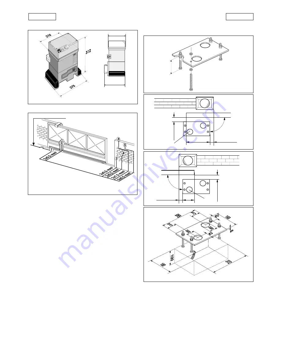
2. DIMENSIONS
Fig. 2
Values are expressed in mm.
3. ELECTRICAL SET-UP (standard system)
4. INSTALLING THE AUTOMATION
4.1.
PRELIMINARY CHECKS
For safe, correct operation of the automation, make sure that
the following requirements are met:
•
The gate’s structure must be suitable for automation. Take
special care to ensure that the wheels are large enough to
support the full weight of the gate, that a top runner is
installed and that physical limit stops are fitted to prevent
the gate from coming off the runner.
•
The characteristics of the ground must ensure sufficient
support for the foundation plinth.
•
There must be no pipes or electrical cables in the area to be
dug for installing the foundation plinth.
•
If the gear motor is located in a vehicle transit area, it is
advisable to provide protection against accidental colli-
sions.
•
Check that there is an efficient ground point for the gear
motor connection.
4.2.
INSTALLING THE BASE PLATE
1) Assemble the base plate as shown in Fig.4.
2) The base plate must be positioned as shown in Fig. 5 (right-
handed closure) or Fig. 6 (left-handed closure) to ensure
that the pinion and rack mesh correctly.
3) Prepare a foundation plinth as shown in Fig. 7 and install the
base plate providing one or more conduits for electrical
cables. Use a level to check that the plate is perfectly
horizontal and wait for the cement to set.
4) Lay the electrical cables for connection to the accessories
and the electricity supply as shown in Fig. 3. For ease of
connection, ensure that the cables protrude by about
40 cm from the hole in the base plate (Figs. 5-6 ref.
1
).
Fig. 7
Fig. 4
Fig. 5
Fig. 6
155
191
230V~ 3x1,5 mm
2
63
225
90
°
49
0
÷
50
49
0
÷
50
155
90
°
a
746 operator with
746 MPS control unit
b
Photocells
c
Key switch
d
Flashing light
e
Radio receiver
1
1
1
1
1
1
1
1
1
1
4.3.
MECHANICAL INSTALLATION
1) Fix the angle bars and the vibration dampers to the opera-
tor as shown in Fig. 8.
2) Open the cover of the operator by unscrewing the 4
retaining screws.
3) Fix the operator to the base plate using the nuts and
washers supplied (Fig. 9).
During this operation, route the cables through the conduit
in the lower half of the operator (Fig. 10).
To access the electronic equipment, route the cables
through the holes provided using the grommets supplied.
4) Adjust the height of the feet and the distance from the
gate as shown in Fig. 11.


