


ground lugs (continued)
connecting to ground terminal
guidelines
battery replacement
H
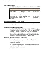
halt operation
halting the unit
hard-wired failover
hardware
AC-powered equipment
DC-powered equipment
hardware requirements
for peripherals
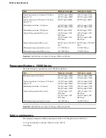
hardware specifications
for i10000 Series platforms
for i11000 Series platforms
for i5000 Series platforms
for i7000 Series platforms
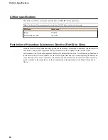
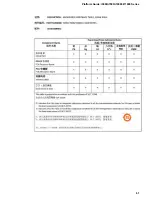
hazardous substance restrictions, See China RoHS Directive
standards.
hot swap
and AC power supplies
and DC power supplies
and transceiver modules
power supplies
I
indicator LEDs
installation
guidelines
performing using serial console
recommendations for
spacing between units
interfaces
about
configuring
duplex mode
for QSFP+
media type
viewing status of a specific interface using tmsh
viewing status of all interfaces using Configuration utility
viewing status of all interfaces using tmsh
viewing valid media types
viewing valid media types using tmsh
J
jumbo frames
L
LCD
about
about using
menu options
putting into menu mode
removing the protective film
using to configure the management IP address
LCD brightness
configuring
configuring using the LCD
LCD menus
Alerts menu options
and Options menu options
Setup menu options
System menu options
LED
network interface
LEDs
about
alarm
chassis power
defining custom alerts
power supply, AC
power supply, DC
status
license
configuring
Locator LED
configuring using the LCD
low voltage directive
M
maintenance
and replaceable components
fan tray
replacing AC power supplies in a single supply system
replacing AC power supply unit in a dual supply system
replacing DC power supply units in a dual supply system
,
management interface
configuring using the LCD
connecting Ethernet cable
enabling or disabling DHCP
setting the gateway
setting the routing prefix
management IP addresses
configuring using LCD
memory technologies
about
battery-backed volatile memory
volatile memory
N
negative pressure fan system
network interface LEDs
Index
70
Содержание i5000 Series
Страница 1: ...Platform Guide i5000 i7000 i10000 i11000 Series MAN 0633 05...
Страница 2: ......
Страница 51: ...Figure 17 Airflow in iSeries platforms Platform Guide i5000 i7000 i10000 i11000 Series 51...
Страница 52: ...Environmental Guidelines 52...
Страница 61: ...Platform Guide i5000 i7000 i10000 i11000 Series 61...
Страница 62: ...Platform Specifications 62...
Страница 64: ...Repackaging Guidelines 64...