INSTALLATION INSTRUCTIONS NIPPER - JULY 2020
32
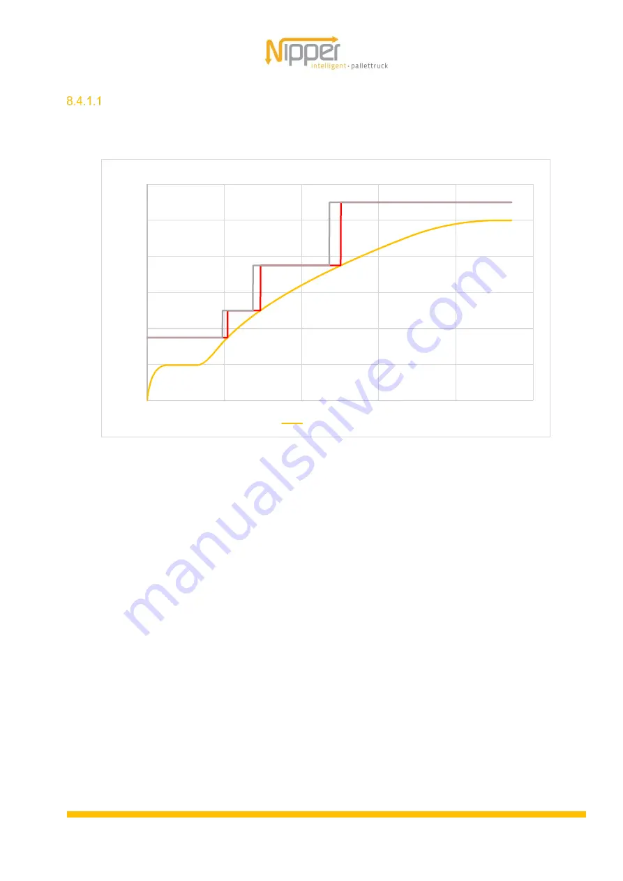
Protective field switching
Figure 15 illustrates the protective field switching.
Figure 14: Protective field switching
0
200
400
600
800
1000
1200
0
500
1000
1500
2000
2500
v
[m
m
/s
]
s [mm]
Protective field switching
v Kufe


