OPERATION AND SERVICE INFORMATION
Page 12
Owner’s Manual and Service Guide
Read all of manual to become thoroughly familiar with this vehicle. Pay particular attention to all Notes, Cautions and Warnings
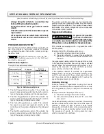
jack stands at the areas indicated only.
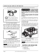
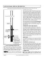
To raise the entire vehicle, install chocks in front and
behind each front wheel (Ref. Fig. 17 on page 12). Cen-
ter the jack under the rear frame crossmember. Raise
the vehicle enough to place a jack stand under the outer
ends of the rear axle.
Lower the jack and test the stability of the vehicle on the
two jack stands.
Place the jack at the center of the front axle. Raise the
vehicle enough to place jack stands under the frame
crossmember as indicated.
Lower the jack and test the stability of the vehicle on all
four jack stands.
If only the front or rear of the vehicle is to be raised, place
the chocks in front and behind each wheel not being
raised to stabilize the vehicle.
Lower the vehicle by reversing the lifting sequence.
WHEELS AND TIRES
Tire Repair
Tool List
Qty. Required
Lug wrench, 3/4" ......................................................... 1
Impact socket, 3/4", 1/2" drive .....................................1
Impact wrench, 1/2" drive ............................................1
Torque wrench, 1/2" drive............................................1
A tire explosion can
cause severe injury or
d eath. Never exceed
inflation pressure rating on tire sidewall.
To reduce the possibility of tire explosion, pres-
surize tire with small amount of air applied inter-
mittently to seat beads. Due to the low volume of
the small tires, overinflation can occur in sec-
onds. Never exceed the tire manufacturer’s rec-
ommendation when seating a bead. Protect face
and eyes from escaping air when removing valve
core.
To reduce the possibility of severe injury caused
by a broken socket when removing wheels, use
only sockets designed for impact wrench use.
Use caution when inflating tires. Overinflation
could cause the tire to separate from the wheel or
cause the tire to explode, either of which could
cause severe injury.
Use caution when inflating tires. Due to the low volume of
the small tires, overinflation can occur in seconds. Over-
inflation could cause the tire to separate from the wheel
or cause the tire to explode.
Tire inflation should be determined by the condition of
the terrain. See GENERAL SPECIFICATIONS section
for recommended tire inflation pressure. For outdoor
applications with major use on grassy areas, the follow-
ing should be considered. On hard turf, it is desirable to
have a
slightly
higher inflation pressure. On very soft
turf, a lower pressure reduces the possibility of tires cut-
ting into the turf. For vehicles being used on paved or
hard surfaces, tire inflation pressure should be in the
higher allowable range, but under no condition should
inflation pressure be higher than recommended on tire
sidewall.
All four tires
should have the same pressure
for optimum handling characteristics. Be sure to install
the valve dust cap after checking or inflating.
The vehicle is fitted with low pressure tubeless tires
mounted on one piece rims; therefore, the most cost
effective way to repair a puncture in the tread is to use a
commercial tire plug.
Tire plug tools and plugs are available at most
automotive parts outlets and have the advan-
tage of not requiring the tire be removed from the wheel.
Fig. 17 Lifting the Vehicle
Ref Liv 2
View from Underside of Vehicle
Center of
Front Axle
Flat Portion
of Frame
Outside End
of Rear Axle
!
!
Содержание INDUSTRIAL 1000 2004
Страница 8: ...Page vi TABLE OF CONTENTS Owner s Manual and Service Guide...
Страница 12: ...Owner s Manual and Service Guide SAFETY INFORMATION Page x Notes...
Страница 43: ...Page 27 GENERAL SPECIFICATIONS Owner s Manual and Service Guide GENERAL SPECIFICATIONS...
Страница 50: ...Page 34 Owner s Manual and Service Guide GENERAL SPECIFICATIONS Notes...
Страница 51: ...Page 35 Owner s Manual and Service Guide WARRANTY LIMITED WARRANTIES...
Страница 54: ...Page 38 Owner s Manual and Service Guide WARRANTY Notes...
Страница 55: ...Page 39 Owner s Manual and Service Guide DECLARATION OF CONFORMITY DECLARATION OF CONFORMITY EUROPE ONLY...
Страница 56: ...Page 40 Owner s Manual and Service Guide DECLARATION OF CONFORMITY...
Страница 57: ...Page 41 DECLARATION OF CONFORMITY Owner s Manual and Service Guide NOT AVAILABLE AT TIME OF PUBLICATION...
Страница 58: ...Page 42 Owner s Manual and Service Guide DECLARATION OF CONFORMITY Notes...
Страница 59: ...Appendix A 1 LABELS AND PICTOGRAMS Owner s Manual and Service Guide LABELS AND PICTOGRAMS...
Страница 64: ...Appendix A 6 Owner s Manual and Service Guide LABELS AND PICTOGRAMS MAXIMUM TAILGATE LOAD 51 Ref Pic 1 4...
Страница 72: ...Sivu vi SIS LLYSLUETTELO K ytt ja huolto ohje...
Страница 76: ...K ytt ja huolto ohje TURVALLISUUSOHJEITA Sivu x Muistiinpanoja...
Страница 107: ...Sivu 27 TEKNISET TIEDOT K ytt ja huolto ohje TEKNISET TIEDOT...
Страница 114: ...Sivu 34 K ytt ja huolto ohje TEKNISET TIEDOT Muistiinpanoja...
Страница 115: ...Sivu 35 K ytt ja huolto ohje TAKUU RAJOITETTU TAKUU...
Страница 118: ...Sivu 38 K ytt ja huolto ohje TAKUU Muistiinpanoja...
Страница 119: ...Sivu 39 K ytt ja huolto ohje YHDENMUKAISUUSJULISTUS YHDENMUKAISUUSJULISTUS VAIN EUROOPPA...
Страница 120: ...Sivu 40 K ytt ja huolto ohje YHDENMUKAISUUSJULISTUS...
Страница 121: ...Sivu 41 YHDENMUKAISUUSJULISTUS K ytt ja huolto ohje EI SAATAVILLA JULKAISUHETKELL...
Страница 122: ...Sivu 42 K ytt ja huolto ohje YHDENMUKAISUUSJULISTUS Muistiinpanoja...
Страница 123: ...Liite A 1 KILVET JA KUVAT K ytt ja huolto ohje KILVET JA KUVAT...
Страница 128: ...Liite A 6 K ytt ja huolto ohje KILVET JA KUVAT SUURIN MAHDOLLINEN TAKALUUKUN KUORMITUS 51 Ref Pic 1 4...

