


4
TLP Pro 1220TG, TLP Pro 1520TG, and TLP Pro 1720TG • Setup Guide
Rear Panel Features
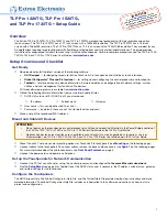
Figure 5 shows the TLP Pro 1720TG rear panel diagram (with back cover removed). The features of the TLP Pro 1220TG and TLP
Pro 1520TG are very similar.
B
B
F
F
E
E
D
D
A
A C
C
I
I
H
H
G
G
J
J
K
K
B
B
F
F
E
E
D
D
A
A
C
C
I
I
H
H
G
G
J
J
K
K
Figure 5.
TLP Pro 1720TG Rear Panel (with back cover removed)
A
Power supply input
— connect a 12 VDC, 3.0 A Limited Power Source (LPS) power supply to this DC plug connector.
ATTENTION:
•
The touchpanels can use a 12 VDC desktop power supply or Power over Ethernet. Do not connect either power
supply before reading the Attention in the Power section of the
TLP Pro 1220, TLP Pro 1520, and TLP Pro 1720
Series User Guide
.
•
Les écrans tactiles peuvent utiliser une source d’alimentation externe 12 Vcc ou l’alimentation POE via Ethernet.
Ne branchez pas de sources d’alimentation externes avant d’avoir lu les mises en garde dans la section
« Power Supply » du
TLP Pro 1220, TLP Pro 1520, and TLP Pro 1720 Series User Guide
.
B
USB connectors
— for peripheral controls.
C
Rear status light
— an LED light bar that can be programmed to provide system feedback.
D
HDMI input
— for alternative video input.
E
XTP/LAN/PoE input
z
XTP
input — Connect the touchpanel to the XTP source using a twisted
pair cable, terminated with an RJ-45 connector. For complete information
about which cables to use, see the user guide for your XTP product.
z
LAN
input — Connect the touchpanel to the LAN using a twisted pair
cable, terminated with an RJ-45 connector.
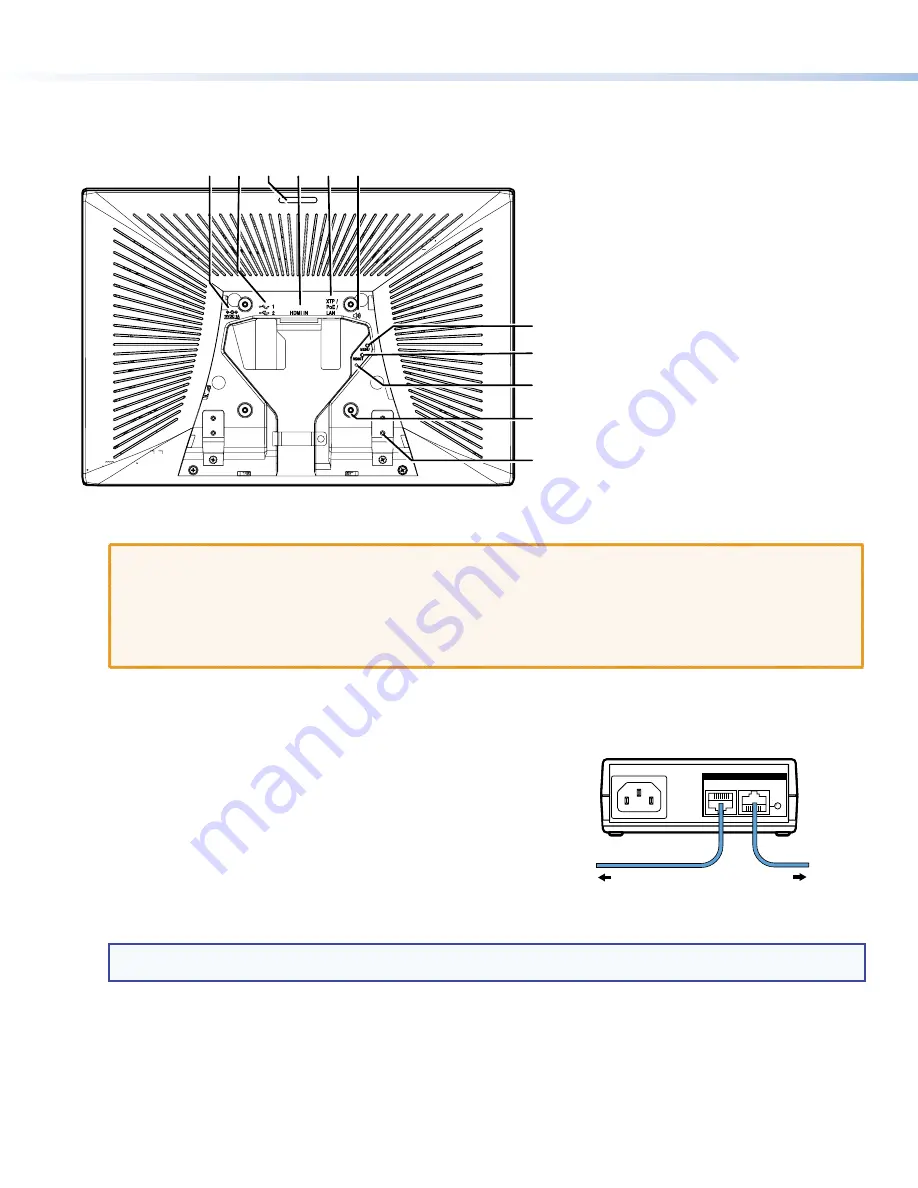
z
PoE
input — the connector can be used with a PoE power injector.
Connect the cables as shown in figure 6, which shows the Extron PI 140
power injector (recommended by Extron).
An Extron IP Link Pro control processor must also be connected to the same
network as the TouchLink Pro touchpanel.
NOTE:
Do not remotely power the touchpanel using an XTP device. Use the power supply or power injector recommended
by Extron (see the
TLP Pro 1220, TLP Pro 1520, and TLP Pro 1720 Series User Guide
).
100-240V~50/60 Hz
1.1A MAX
INPUT
OUTPUT
POWERED TLP
LAN
To Network or
XTP Device
To a TLP Pro
touchpanel
Extron PI 140
Figure 6.
Connecting the Power Injector
F
Audio output
— for use with headphones or assistive listening devices.
G
Menu button
— activates the setup menu and calibration screen (see
H
Reset button
— pressing the reset button allows the unit to be reset in any of three different modes (see
, on the
following page. For more information, see the
TLP Pro 1220, TLP Pro 1520, and TLP Pro 1720 Series User Guide
).
I
Reset LED
— provides feedback about the reset status when the user presses the reset button.
J
VESA mounting holes
(4) — for use with D-type VESA mounting kits with the 100 x 100 mm mounting pattern.
K
Base attachment hinge
(2) — each hinge secures the touchpanel to the base with two screws.


