SW VGArs / Ars Series Switchers • Operation
SW VGArs / Ars Series Switchers • Operation
Operation
Front Panel Controls and Indicators
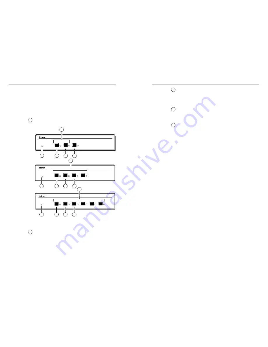
Figure 3-1 shows the controls and indicators on the front panel
of the SW6 VGArs / Ars Series switchers. The front panels are
identical for the non-audio (SW VGArs) and audio (SW VGA Ars)
models.
Front panel buttons and LEDs
1
Auto Switch Active LED
— When this LED is on, it
indicates that the auto switch mode is active.
SW VGA/Ars SERIES
VGA/AUDIO SWITCHER
AUTO SWITCH
ACTIVE
2
1
MODE
NORMAL
AUTO
SW VGA/Ars SERIES
VGA/AUDIO SWITCHER
AUTO SWITCH
ACTIVE
4
3
2
1
MODE
NORMAL
AUTO
SW VGA/Ars SERIES
VGA/AUDIO SWITCHER
AUTO SWITCH
ACTIVE
6
5
4
3
2
1
MODE
NORMAL
AUTO
2
3
4
5
3
4
5
3
1
1
1
4
5
2
2
Figure 3-1 — Front panel (SW VGArs and SW VGA Ars
front panels are identical).
2
Input selection buttons and LEDs
— When the auto
switch mode is off, use these buttons to select the input.
The LED for the selected input lights.
The LEDs continue to indicate the selected input when
auto switch mode is on. If no input LED is lit, no input has
active sync pulses and no input is selected.
3
Mode button
— Use this button, with either the Auto or
the Normal button, to manually turn auto switch mode on
or off.
Mode is a secondary function of the Input 1 button.
4
Normal button
— Use this button, with the Mode button,
to manually turn auto switch mode off.
Normal is a secondary function of the Input 2 button.
5
Auto button
— Use this button, with the Mode button, to
manually turn auto switch mode on.
On 4-input and 6-input switchers, Auto is a secondary
function of the Input 3 button.
Front Panel Operations
Plug in all system components and turn on the input devices
(desktop computers, laptops, etc.) and the output monitor.
Select an input. The image should appear on the monitor.
Normal and auto switch modes
All SW VGArs / Ars Series switchers can operate in either
normal (manual switch) mode or auto switch mode. In auto
switch mode, the highest numbered input with a sync signal
present is automatically selected for output. If no sync signal is
present, no input is selected. Input selection by the front panel
buttons is blocked while the switcher is in auto switch mode.
However, the front panel LEDs remain functional and the
buttons can be used to view or change the mode.
Viewing the current switch mode
You can determine the current switch mode at any time by
noting the state of the Auto Switch Active LED. This LED is lit
if the switcher is in auto switch mode.
Selecting normal switch mode
Press and hold the Input 1/Mode button while you press and
release the Input 2/Norm button. The Auto Switch Active LED
turns off, indicating normal switch mode. Release the
Input 1/Mode button.
Selecting auto switch mode
Press and hold the Input 1/Mode button while you press and
release the Input 3/Auto button. The Auto Switch Active LED
turns on, indicating auto switch mode. Release the
Input 1/Mode button.
3-2
3-3
im Vertrieb von
CAMBOARD Electronics
www.camboard.de
Tel. 07131 911201
Fax 07131 911203


