MGP Pro Series • Installation
8
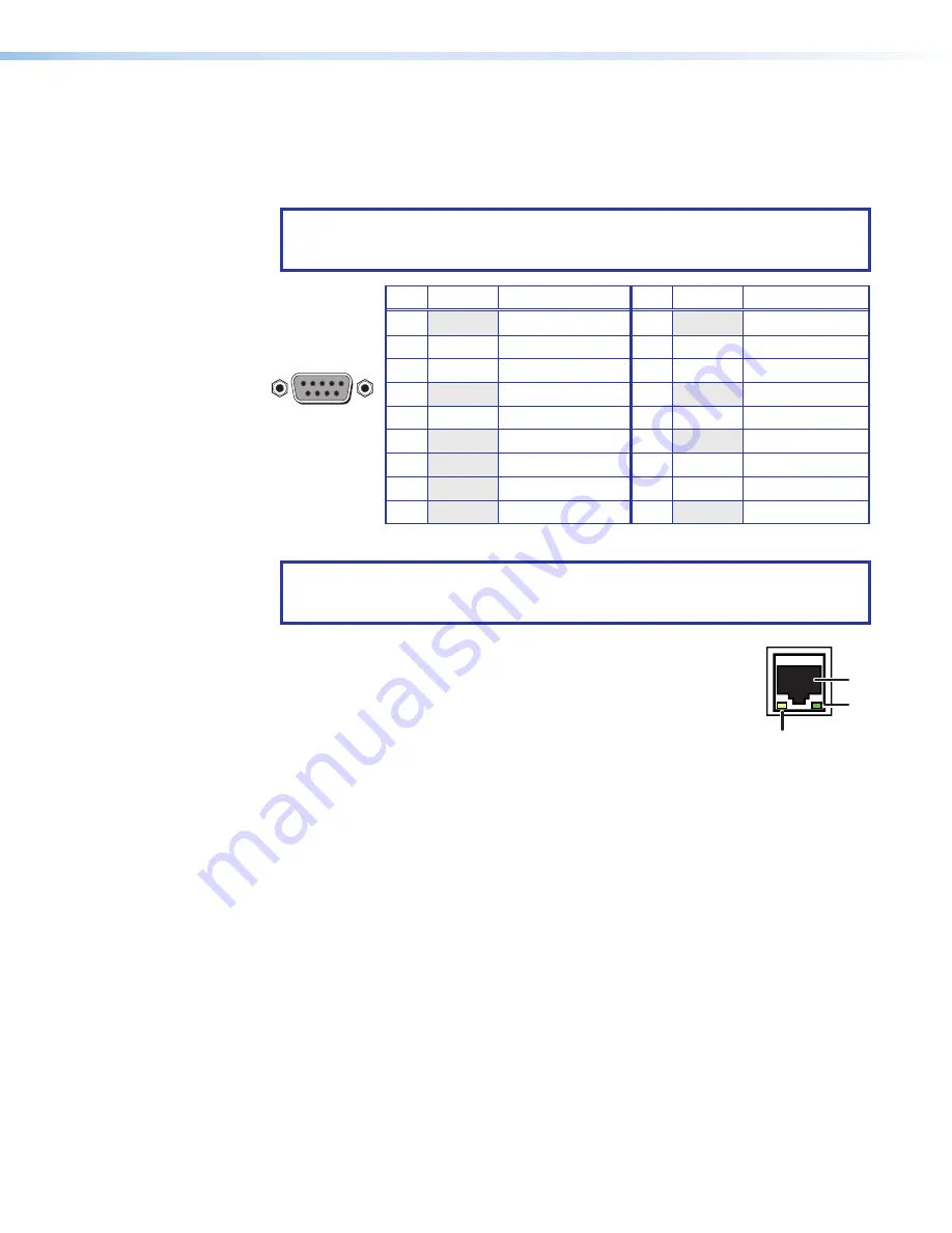
Remote RS-232/422 connector
— (see
on page 6) Plug a
computer or other RS-232 or RS-422 host device into this female 9-pin D connector.
Wire the connector as shown in figure 6 (see the
Remote Configuration and Control
starting on page 42 for more information on controlling the MGP Pro remotely via
RS-232 or RS-422).
NOTE:
The MGP Pro also has an RS-232-only Config port on a 2.5 mm tip-ring-
sleeve (TRS) connector on the front panel. For information on this port, see
J
RS-232 / 422
5
1
9
6
Female
Pin RS-232
Function
Pin RS-422
Function
1
—
Not used
1
—
Not used
2
Tx
Transmit data
2
Tx–
Transmit data (–)
3
Rx
Receive data
3
Rx–
Receive data (–)
4
—
Not used
4
—
Not used
5
GND
Signal ground
5
GND
Signal ground
6
—
Not used
6
—
Not used
7
—
Not used
7
Rx+
Receive data (+)
8
—
Not used
8
Tx+
Transmit data (+)
9
—
Not used
9
—
Not used
Figure 6.
RS-232/422 Connector Pin Configuration
NOTE:
The cables used to connect the RS-232/422 port to a computer or control
system may need to be modified by removing pins or cutting wires. If unneeded
pins are connected, the processor may cease functioning.
LAN connector
— Plug an RJ-45 network cable into this connector
LAN
1
2
3
to connect the unit to a network (via a switch, hub, or router) or to a
single computer (see the RJ-45,
1
, in the image on the right).
1
Activity LED
— This LED blinks to indicate network activity.
2
Link LED
— This LED lights to indicate a good network
connection.
Use a straight-through cable to connect to a network or a crossover cable to connect
directly to a computer.
•
For 10BaseT (10 Mbps) networks, use a CAT 3 or better cable.
•
For 100BaseT (maximum 155 Mbps) networks, use a CAT 5 cable.
on the next page for LAN port wiring information.
Remote RS-232/422 connector
6
LAN connector


