background image

FOX3 SR 201 Scaling Receiver • Installation

5


Installation

This section details the installation of the FOX3 SR 201 receiver, including:

• 

Installation Overview

• 

Rear Panel Features

• 

Connector and Cable Details

Installation Overview

Follow these steps to install and set up an Extron FOX3 SR 201 receiver for operation:

c

  Turn off all of the equipment. Ensure that the video source and the output display are all 

turned off and disconnected from the power source.

c

  Mount the receiver (see 

Equipment Mounting

 on page 47).

c

  Connect the cables and configure the units.

c

  Plug in the power supplies, then turn on the display and the input.

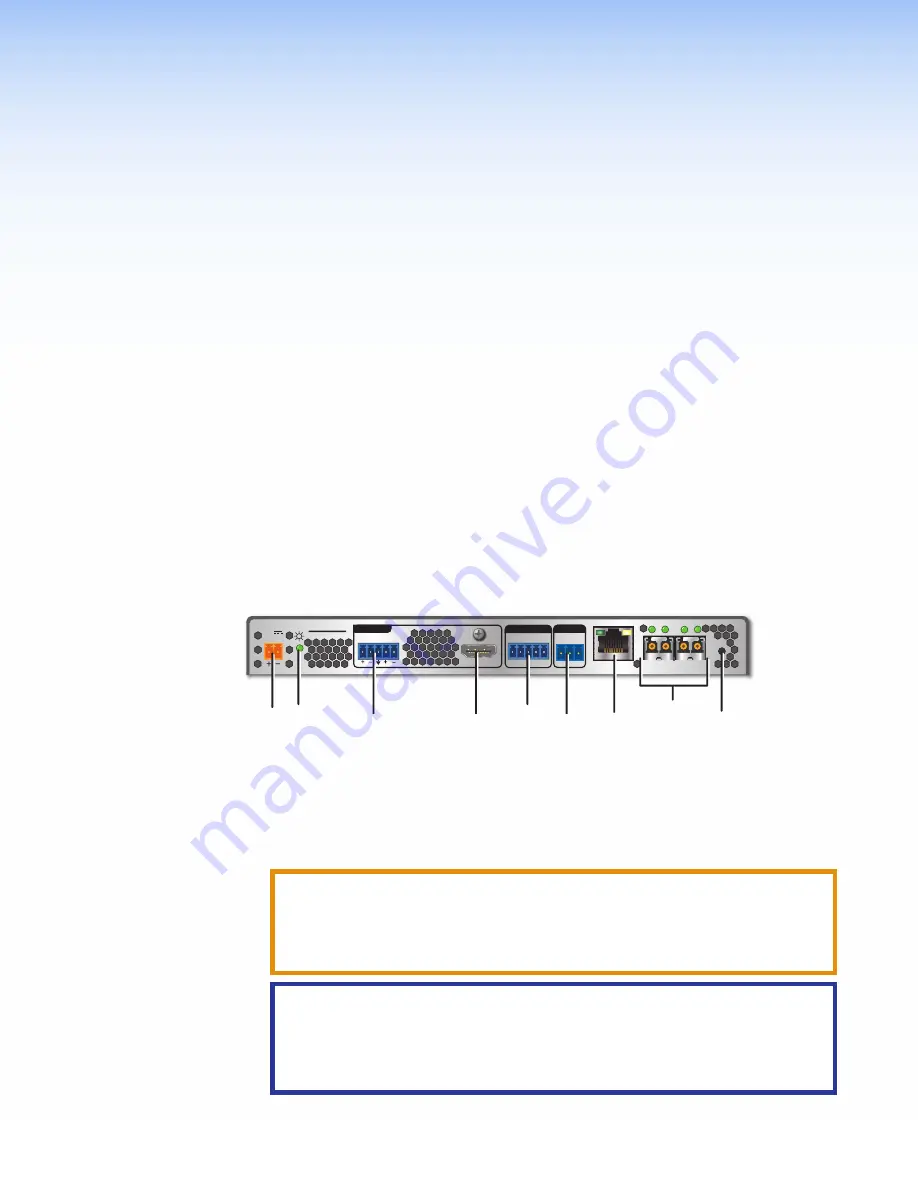
Rear Panel Features


RS-232

REMOTE

POWER

12V

2.0 A MAX

Tx Rx G

A

OUT IN

B

OUT IN

LAN

RS-232

Tx Rx

Tx Rx

G

IR

HDMI

FOX3 SR 201

R

AUDIO

CONTROL

OUTPUTS

I

I

I

G

G

G

F

F

F

C

C

C

A

A

A

D

D

D

H

H

H

E

E

E

B

B

B

Figure 2. 

FOX3 Scaling Receiver Rear Panel Features

A

  Power inlet

D

  HDMI output

G

  LAN Ethernet port

B

  Power LED

E

  Control RS-232/IR port

H

  SFP module and LEDs

C

  Audio output

F

  Remote RS-232

I

  Reset button

A


Power inlet

 — Connect the external 12 V power supply to the 2-pole captive screw 

inlet (see 

Power Connector

 on page 9 for wiring instructions).

CAUTION:

  The DC output cables must be kept separate from each other while the 

power supply is plugged in. Remove power before wiring

ATTENTION :


Les câbles de sortie CC doivent être séparés les uns des autres 

tant que la source d’alimentation est branchée. Coupez l’alimentation avant 
d’effectuer les raccordements.

ATTENTION:

• 

Do not connect any external power supplies until you have read the 

Attention


on page 10.

• 

Veuillez lire les encadrés « 

Attention

 on page 10 » à partir ci-dessous avant 

de brancher une source d’alimentation externe.


Содержание FOX3 SR 20

Страница 1: ...User Guide FOX3 SR 201 Fiber Optic Extender Fiber Optic HDMI Scaling Receiver 68 2888 01 Rev A 05 21...

Страница 2: ...Safety Instructions...

Страница 3: ...PowerCage PURE3 Quantum ShareLink Show Me SoundField SpeedMount SpeedSwitch StudioStation System INTEGRATOR TeamWork TouchLink V Lock VideoLounge VN Matrix VoiceLift WallVault WindoWall XPA XTP XTP Sy...

Страница 4: ...pile D barrassez vous des piles usag es selon le mode d emploi Class 1 Laser Product Any service to this product must be carried out by Extron and its qualified service personnel CAUTION Using contro...

Страница 5: ...examples of computer or device responses used in this guide the character 0 is the number zero and O is the capital letter o Computer responses and directory paths that do not have variables are writ...

Страница 6: ......

Страница 7: ...nfiguration 20 Audio De embedding 20 Audio Output Volume 20 Audio Mute 20 SIS Configuration and Control 21 Host Control Ports 21 Rear Panel RS 232 Port 21 Front Panel Configuration USB Port 21 Etherne...

Страница 8: ...FOX3 SR 201 Scaling Receiver Contents viii Equipment Mounting 47 Mounting the Scaling Receiver 47 Tabletop Use 47 Mounting kits 47 UL Rack Mounting Guidelines 47...

Страница 9: ...Receiver is an ultra high performance fiber optic receiver to accept proprietary optical signals from long haul transmission of the following over two fiber optic cables see figure 1 on page 2 Uncomp...

Страница 10: ...x G A OU T IN B OU T IN LA N RS 23 2 Tx Rx Tx Rx G IR HD MI FO X3 SR 20 1 R AU DIO CO NT RO L OU TP UT S CO NT RO L RS 23 2 RE MO TE PO WE R 12 V A MA X Tx Rx G A OU T IN B OU T IN RS 23 2 Tx Rx Tx Rx...

Страница 11: ...uncompressed 4K video up to 4096x2160 at 60 Hz with 4 4 4 chroma sampling over two fibers Supported HDMI 2 0 specification features include data rates up to 18 Gbps and Deep Color up to 12 bit HDCP 2...

Страница 12: ...itoring Front and rear panel LEDs verify signal presence HDCP authentication fiber link status and power Easy setup and commissioning with Extron s PCS Product Configuration Software Conveniently conf...

Страница 13: ...AUDIO CONTROL OUTPUTS I I I G G G F F F C C C A A A D D D H H H E E E B B B Figure 2 FOX3 Scaling Receiver Rear Panel Features A Power inlet D HDMI output G LAN Ethernet port B Power LED E Control RS...

Страница 14: ...NOTE If only one fiber optic cable is connected see figure 3 on page 7 RS 232 or IR reports from the controlled device cannot be recieved To receive responses from the controlled device two fiber opti...

Страница 15: ...ver Inputs A 2 Output B is available to transmit a 4K 60 Hz uncompressed signal when the FOX3 4K 60 Hz Uncompressed Video LinkLicense is purchased 1 Port A Out required For all one way video audio and...

Страница 16: ...HDMI connection mounting screw from the panel enough to allow the LockIt lacing bracket to be placed over it 2 The screw does not have to be removed 3 Place the LockIt lacing bracket on the screw and...

Страница 17: ...the exposed wires and tinning the wires Power Connector CAUTION The DC output cables must be kept separate from each other while the power supply is plugged in Remove power before wiring ATTENTION Le...

Страница 18: ...ource marked Class 2 or LPS rated 12 VDC 1 7 A minimum Si le produit n est pas fourni avec une source d alimentation il doit tre utilis avec une source d alimentation certifi e UL de classe 2 ou LPS a...

Страница 19: ...et cables are limited to a length of 328 feet 100 meters NOTES Do not use standard telephone cables Telephone cables do not support Ethernet or Fast Ethernet Do not stretch or bend cables Transmission...

Страница 20: ...l is HDCP encrypted D Menu and Enter buttons Press these buttons to access and navigate the on screen display menu system E Navigation buttons Press these buttons to navigate through the on screen dis...

Страница 21: ...ID USB 2 0 USB 1 2 MENU ENTER HOST F 2 2 2 1 1 1 3 3 3 5 5 5 4 4 4 6 6 6 Figure 9 Menu Selection Buttons Press the Up 3 or the Down 4 arrow button to navigate submenus or submenu items Press the Left...

Страница 22: ...reen Menu 4 Press Enter to select the item 5 Press the button to return to the list of submenus in the left panel To adjust the settings of a submenu item 1 Navigate to an adjustable submenu item and...

Страница 23: ...signal information for all outputs Setup Submenu Figure 12 Quick Setup Submenu The Quick Setup submenu is displayed by default when the OSD opens and provides quick access to frequently used settings...

Страница 24: ...ied values while retaining all TCP IP settings To reset using the OSD menu press and hold the Enter button until Factory Reset is displayed approximately 5 seconds The message remains for approximatel...

Страница 25: ...on about 6 seconds until the Power LED blinks twice Then release and press the Reset button momentarily 1 second again within 1 second Sets the following back to factory default Port mapping IP addres...

Страница 26: ...les are available in PCS when a device is connected or an offline device is selected EDID The FOX3 scaler has one store slot assigned to an input By default the EDID is set to 1080p 60 Hz with 2 chann...

Страница 27: ...configure the RS 232 Insertion via PCS The control system then sends a control command Into the transmitter Control RS 232 port Out of the transmitter SFP A port to the receiver SFP A IN port To the...

Страница 28: ...st the overall output volume level for the receiver analog audio output as well as the embedded LPCM 2CH audio on the HDMI output via PCS see the FOX3 SR 201 Help File or SIS command see Audio output...

Страница 29: ...s Rear Panel RS 232 Port The FOX3 devices have a rear panel serial port see figure 2 on page 5 that can be connected to a host device such as a computer running Extron DataViewer available at www extr...

Страница 30: ...ice responds with a copyright message including the copyright year the name of the product firmware version part number and the current date and time If the login and password are incorrect the Login...

Страница 31: ...are version number 60 nnnn nn is the part number NOTE This message only displays if the FOX3 device is connected to the serial port Error Responses When the scaling receiver receives a valid SIS comma...

Страница 32: ...epresent variables in the command and response fields Command and response examples are shown throughout the table The ASCII to HEX conversion table below is for use with the command and response tabl...

Страница 33: ...ace only the first letter required X1 Data bits 7 8 default X1 Stop bits 1 default 2 X1 UARTs 1 Endpoint X1 Verbose mode 0 Clear none default for Ethernet 1 Verbose mode default for for RS 232 2 Tagge...

Страница 34: ...00 14 1280x1024 15 1360x768 16 1366x768 17 1440x900 18 1400x1050 19 1600x900 20 1680x1050 21 1600x1200 22 1920x1200 23 480p 24 25 576p 26 720p 29 30 31 32 33 34 1080i 35 36 37 1080p 38 39 40 41 42 43...

Страница 35: ...1 Mute X3 View audio output 1 Digital 2 Analog Information requests View firmware version Q q Verbose mode 2 3 x xx Ver 01 x xx View full firmware version Q q Verbose mode 2 3 x xx xxxx Bld x xx xxxx...

Страница 36: ...X2 Fiber optic mode SM or MM DHCP client Set DHCP on or off EX1 DH IdhX1 View DHCP status EDH X1 KEY X1 Set DHCP 0 Off default 1 On Telnet port Set Telnet port map EZX3 PMAP PmapZX3 View Telnet port m...

Страница 37: ...set audio gain attenuation to default levels Global unsolicited responses Input change Reconfig Any change of the input frequency or a power cycle Fiber link Sts02 X1 X2 Any change in fiber link statu...

Страница 38: ...o 1 Fill default 2 Follow Freeze Set freeze X3 F FrzX3 Turn on or off freeze setting View current freeze setting F Verbose mode 2 3 X3 FrzX3 KEY X3 On or off 0 Off default 1 On Executive mode front pa...

Страница 39: ...tall the PCS software NOTES Also download the latest versions of software and firmware for your product An Extron Insider account is required to download and use PCS Contact an Extron support represen...

Страница 40: ...e FOX3 SR 201 c Optional Click Release Notes 2 for more information about the firmware update d Click Download 3 The product download screen opens e Enter the required user information and click Downl...

Страница 41: ...nection method 1 Open the Product Configuration Software program from the desktop shortcut The Extron PCS window opens to the Device Discovery panel see figure 20 Figure 20 Device Discovery Panel 2 Se...

Страница 42: ...e been set to the device serial number In the event of a complete system reset the passwords convert to the default which is extron see Roles and Permissions Panel on page 44 to change a password 4 In...

Страница 43: ...Device Models list 3 Click the Configure button A new offline device configuration tab opens Software Overview NOTE For details about specific software features see the FOX3 SR 201 PCS Help File Figu...

Страница 44: ...the Software menu select Software Settings The Software Settings dialog box opens Figure 28 Software Settings Dialog Box 2 Click the Re enable Confirmation Dialogs button see figure 28 1 The dialog bo...

Страница 45: ...s about third party software packages and associated licensing click Licenses 2 4 Click the OK button 3 to close the dialog box Exit Disconnect connected devices and close the application 1 From the S...

Страница 46: ...e dialog box with selectable modes for resetting the connected device as well as the Unit Information also displayed in the Hardware Settings dialog box NOTE The factory configured passwords for all a...

Страница 47: ...stallation on page 31 Update Firmware to this Device Upload firmware from the host device to the connected device only Update Firmware to Multiple Devices Upload firmware to multiple devices on the ne...

Страница 48: ...figure 8 on page 12 2 Open a web browser on a PC connected on the same LAN or WAN or connected to the front panel USB port NOTE Compatible web browsers are Microsoft Edge Modzilla Firefox Google Chro...

Страница 49: ...kLicense Panel The panels that can be edited have an EDIT link to click to access the panel To view general information about the FOX3 SR 201 click the ABOUT link 7 About the FOX3 SR 201 Figure 33 FOX...

Страница 50: ...tus panel see figure 33 2 on page 41 displays the current date time time zone the amount of time the device has been running Uptime and the internal temperature in degrees Celsius To set the date and...

Страница 51: ...sk 4 and Gateway address 5 click in the desired field and enter the address 3 When finished editing click out of the field and click SAVE to confirm your changes or CANCEL to close the window without...

Страница 52: ...nel The Roles and Permissions panel see figure 33 5 on page 41 displays whether Admin and User passwords have been set It does not display the actual password NOTE The following rules apply to passwor...

Страница 53: ...fields cannot be blank Figure 40 Passwords Dialog Box LinkLicense Panel The LinkLicense panel see figure 33 6 on page 41 displays information about any LinkLicense applied to the FOX3 device A LinkLi...

Страница 54: ...33 7 on page 41 to open the About dialog box to view general information about the FOX3 SR 201 such as the firmware version copyright part number licenses patents and web page version Click on the Vi...

Страница 55: ...it into a rack Elevated operating ambient temperature If installed in a closed or multi unit rack assembly the operating ambient temperature of the rack environment may be greater than room ambient Th...

Страница 56: ...does not apply if the fault has been caused by misuse improper handling care electrical or mechanical abuse abnormal operating conditions or if modifications were made to the product that were not aut...

Отзывы: