background image

Command and Responses

Using the Command and Response Tables

The following are either Telnet (port 23) or Web browser (port 80) commands. There are 
some minor differences when you are implementing these commands via Telnet or via 
URL encoding using a Web browser. All commands listed below will work using either 
connection method but, due to some limitations of the Web browser, the encapsulation 
characters are modified to make sure that the Web browser will properly handle them. All 
examples in the tables show proper implementation in a Telnet or Web browser session. 

NOTE:

  Note for Web browsers: all non-alphanumeric characters must be represented 

as their hex equivalent, such as %xx where xx equals the two character 
representation of the hex byte that needs to be sent (for example, a comma 
would be represented as %2C). 

Telnet 

   Web 

Browser 

Escape (Hex 1B)   


W [must not be encoded] 

Carriage Return (Hex 0D)  

Pipe Character ( 


) [must 

not

 be encoded]

When SIS commands are used through a Web browser, the URL reference is used below to 
shorten the examples. This would in practice be the full URL of the control interface and 
Web page reference including all path information.  
For example: http://192.168.254.254/index.html

To send any of the commands using a Web browser you need to prefix them with the full 
URL followed by 

?cmd=.

 See the “URL Encoding” section, later in this chapter.

NOTE:

  With Telnet you can use either the Escape commands or the W commands, and 

the carriage return or the pipe (


) character. With the Web browser you are 

required to use the W commands and the pipe character. 

In either method {Data} = data that is directed to a specified port and must be encoded if 
non-alphanumeric.

The Command and Response table for SIS commands later in this chapter lists the 
commands that the DVS 304 scaler recognizes as valid, the responses that are returned 
to the host, a description of the command’s function or the results of executing the 
command, and an example of each command in ASCII (Telnet) and URL Encoded (Web). 

NOTE:

  Upper and lower case text can be used interchangeably except where noted. 


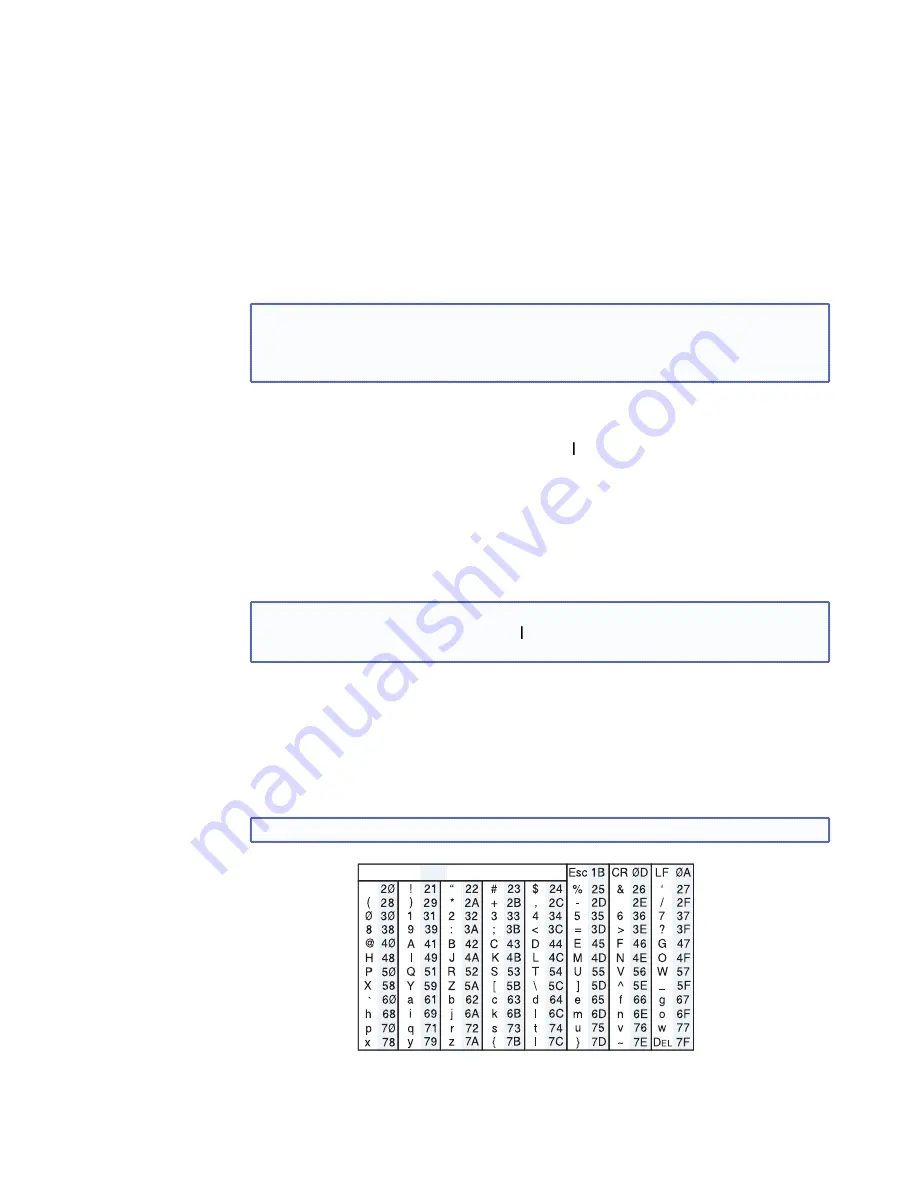
ASCII to HEX  Conversion Table

Figure 28. 

ASCII to Hexadecimal Character Conversion Table

DVS 304 Series • SIS Communication and Control

32

Содержание DVS 304

Страница 1: ...User Guide DVS 304 Series SCALERS AND SCAN CONVERTERS Video and RGB Scalers 68 1039 01 Rev C 01 11 ...

Страница 2: ...nden sollten Sie alle Sicherheits und Bedienungsanleitungen genau durchlesen und verstehen Aufbewahren der Anleitungen Die Hinweise zur elektrischen Sicherheit des Produktes sollten Sie aufbewahren damit Sie im Bedarfsfall darauf zurückgreifen können Befolgen der Warnhinweise Befolgen Sie alle Warnhinweise und Anleitungen auf dem Gerät oder in der Benutzerdokumentation Keine Zusatzgeräte Verwenden...

Страница 3: ... residential area is likely to cause harmful interference in which case the user will be required to correct the interference at his own expense NOTE This unit was tested with shielded cables on the peripheral devices Shielded cables must be used with the unit to ensure compliance with FCC emissions limits For more information on safety guidelines regulatory compliances EMI EMF compliance accessib...

Страница 4: ...ix Switcher 28 Removing the Sync to Matrix Script 28 Minimizing Synchronization Problems Without Using the Sync to Matrix Feature 29 SIS Communication and Control 30 Host to Scaler Communications 30 Scaler initiated Messages 30 Copyright Information 31 Password Information 31 Error Responses 31 Error Response References 31 Command and Responses 32 Using the Command and Response Tables 32 Symbol De...

Страница 5: ...Menu 77 Audio Configuration Menu 77 Memory Preset Menu 77 IP Configuration Menu 78 Advanced Configuration Menu 78 Exit Menu 78 Executive Mode Menu 79 Reference Material 80 Specifications 80 Part Numbers and Accessories 83 Included Parts 83 Optional Parts 83 Serial Digital Interface SDI Card Installation 84 Warranty v DVS 304 Series Contents v ...

Страница 6: ...S video component Y R Y B Y video and RGB video to computer video RGBHV RGBS RGsB or HD component The four inputs of all DVS models accommodate composite video S video component video and RGB The fourth input is fully configurable to accept any available analog video format from composite video to RGBHV Additionally with the exclusive Auto Input Format Detection mode the DVS 304 devices automatica...

Страница 7: ...to input 1 2 3 or 4 the default is none RGB and video scaling Provides a high performance scaling engine with the capacity to scale standard definition video high definition video and computer video signals up or down in resolution Picture control Allows size position brightness contrast color tint detail zoom and pan adjustments for each input Picture In Picture Allows for a low resolution YUVi S...

Страница 8: ...NTSC video the film frame rate has to be matched to the video frame rate in a process called 3 2 pull down Jaggies and other image artifacts can result if conventional de interlacing techniques are used on film source video The digital video scaler s advanced film mode processing recognizes signals that originated from film The scaler then applies video processing algorithms that optimize the conv...

Страница 9: ...70 495 01 is an infrared remote control that replicates most of the front panel controls of the digital video scaler except the Menu and Next buttons SDI input card Serial digital interface SDI input can be added to a DVS 304 model by the installation of an SDI input card part 70 168 01 DVS 304 Series Introduction 4 ...

Страница 10: ...2 9 11 4 Y VID R R Y G Y B B Y RS 232 LAN RESET SDI B Y C RGB R Y Y B Y YC VID 100 240V 3A I N P U T O U T P U T VID 50 60 Hz 1 2 3 R Y H HV V ACT LINK DVI I YC 4 6 7 10 1 9 11 5 12 8 DVS 304 D DVS 304 DVI D DVS 304 DVI AD DVS 304 AD Optional Optional Optional Optional Figure 1 DVS 304 Devices Rear Panel Features a Power input Connect the standard IEC power cord from a 100 to 240 VAC 50 Hz or 60 H...

Страница 11: ...YC Y VID R Y Figure 3 Input 2 Connector Cabling g Video input 3 S video Connect an S video signal to this 4 pin mini DIN female connector h Video input 4 RGB R Y Y B Y YC VID Connect RGBHV RGBS RGsB RGBcvS YUVi YUVp HDTV S video and composite video through this 15 pin HD connector See pin configurations below NOTE DVS 304 DVI models feature EDID emulation on this 15 pin HD connector Signal Input 4...

Страница 12: ... display device to this DVI I connector for scaled RBG or component video digital and analog outputs j Reset button and LED Using an Extron Tweeker pointed stylus or ballpoint pen press this recessed button for manual resets The unit has four modes of reset see Resetting the Unit later in this chapter for additional information The green LED flashes to show the reset mode indicators and that power...

Страница 13: ... Tx Transmit data 3 Rx Receive data 4 Input 2 Contact closure 5 Ground Signal ground 6 Input 3 Contact closure 7 Input 4 Contact closure 8 No connection 9 Reserved Figure 7 RS 232 Pin out The Remote connector also provides a way to select an input using a remote contact closure device Contact closure control uses pins on the RS 232 connector that are not used by the RS 232 interface see preceding ...

Страница 14: ... and composite video NOTE RGB pass through signals at native rate without additional processing are available on analog outputs only The DVI output is disabled for pass through b Menu button Use this button to enter and move through the main menu system for the scaler See the Menus Configuration and Adjustments section for details c Next button Use this button to step through the submenus in the s...

Страница 15: ... and to make adjustment selections Refer to the flowcharts in this chapter and to specific sections for explanations on knob adjustments Menu Overview The default cycle appears on the LCD when no adjustments are actively being made The screens cycle between the screen that shows the active input s number and video format and the current output resolution as shown below DVS 304 xxx xx 2 sec INPUT 1...

Страница 16: ...ELECTRONICS 2 sec DVS 304 xxx xx Displays specific model name for example DVS 304 DVI AD Displays specific model part number for example 60 1027 04 Figure 10 Main Menu To return to the default cycle allow the DVS 304 to time out after 20 seconds Alternatively press the Menu button repeatedly until the Exit menu appears then press the Next button Submenus are accessed from a main menu by pressing t...

Страница 17: ...T Select video format Composite S video YUVi YUVp HDTV YUV Auto Assign SDI to Input 1 2 3 4 none Select video format Composite S video RGBcvS YUVi YUVp HDTV RGB scaled RGB pass Auto detect Aspect ratio options 4 x 3 16 x 9 For YUVp or RGB input only Total pixels Specify the width in pixels of the total image area sampled Pixel phase Adjust the pixel sampling point for a selected input Horizontal s...

Страница 18: ...e DVI output is disabled for RGB pass through For DVS 304 DVI models input 4 has an EDID emulation feature See table on page 15 for EDID values When input 4 is set as auto detect the scaler will switch to the new configuration whenever it detects an input type change The default is RGB scaled SDI input SDI IN Rotate either the Adjust horizontal knob or Adjust vertical knob while in the SDI Input s...

Страница 19: ... Move the zoomed image horizontally or vertically Available only when zoom is set over 100 Horizontal sizing Adjust horizontal image sizing Vertical sizing Adjust vertical image sizing Brightness Adjust image brightness Contrast Adjust image contrast Color Adjust color of image Tint Adjust tint of image Figure 14 Picture Control Menu Output Configuration The output configuration menu allows select...

Страница 20: ...5 x 1024 X X 1366 x 768 X X X 1400 x1050 X X 1600 x 1200 X X 480p X X 576p X X 720p X X X 1080i X X X 1080p X X X X 1440 x 900 X X 1680 x 1050 X 1280 x 800 X X 1080p Sharp X 1920x1200 X 1080p CVT X DVI models only Output Format Using either the Adjust horizontal or Adjust vertical knob select the output video format required by the display RGBHV default RGBS RGsB Y R Y B Y Sync Polarity The displa...

Страница 21: ... The following flowchart provides an overview of the Memory Preset submenus and the options for each setting NEXT IN1 SAVE N A 1 2 3 IN1 CLEAR N A 1 2 3 NEXT NEXT Saving SAVE memory presets Save the currently selected input s picture control information Up to 3 presets per input can be selected and saved N A is the default Save a preset by pressing the Next button Clearing CLR memory presets Clear...

Страница 22: ...ng a preset press Menu Recalling a preset Recalling a saved preset requires that the desired input be currently selected and that the input button be pressed successively to activate each saved preset up to three Each saved preset will display the message Input X Memory Y where X refers to the input 1 to 4 and Y refers to the preset 1 to 3 In the absence of any saved presets the Input X Memory Y m...

Страница 23: ...enu Auto imaging When auto image is on the unit automatically sizes and centers each new input Blue mode When set to on only the sync and blue video signals are passed to the display Auto switching The unit switches to the highest numbered input that has a signal present when auto switching is on RGB delay Can be set from 0 to 5 0 seconds in 0 5 second steps On Screen Display label duration Can be...

Страница 24: ...ler s color and tint level To use this feature set this submenu to On so that only sync and blue video signals will be passed to the display Use either the Adjust horizontal or Adjust vertical knob to select this mode The default state is Off NOTE The Blue mode has no effect for RGB pass through mode on Input 4 Auto switch mode The Auto switch mode causes the highest numbered input having a signal...

Страница 25: ...olor Bars Used to calibrate color settings on the display and to confirm proper system wiring Enhance mode When the enhance mode is set to on automatic gain control of the low resolution input signal is enabled If the input signal level is too weak signal gain is increased and if the input signal level is excessive signal gain is decreased Using either the Adjust horizontal or Adjust vertical knob...

Страница 26: ...ed Off Off Each change in input sync causes default values to be applied to the rate Any manual changes made to the image and picture controls are lost when a new rate is applied Auto Memory 16 per input 64 total Input Configuration Aspect Ratio Film Mode H V Start Phase Total Pixels H V Active H V Pan Picture controls Zoom Color Tint Bright Cont Detail H V Size H V Position Figure 21 Settings Sav...

Страница 27: ...N The parameters of the PIP window are adjustable from the front panel or by SIS commands only Any change in configuration except positioning of the PIP window is saved to that input even after the PIP mode is not longer active The PIP window input is listed under the default cycle on front panel menu as shown below When the PIP window is active size position and picture controls all apply to the ...

Страница 28: ...t Menu From this submenu press the Menu button to return to the Start Auto Image menu cycle or press the Next button to return to the default cycle START AUTO IMAGE ON IN1 MENU MENU INPUT CONFIG MEMORY PRESETS 2 sec INPUT 1 COMPOSITE OUTPUT 1024 x 768 60 Default Cycle 2 sec IP CONFIG MENU MENU ADVANCED CONFIG MENU MENU TO EXIT MENU PRESS NEXT MENU PICTURE CONTROL MENU OUTPUT CONFIG MENU AUDIO CONF...

Страница 29: ...ersion number NOTE User defined Web pages may not work correctly if using an earlier firmware version Run Stop Events 3 Hold down the Reset button for about 3 seconds until the Power LED blinks once then release and press Reset momentarily 1 second within 1 second Mode 3 turns events on or off If the events are currently stopped after the momentary press the power LED flashes twice indicating the ...

Страница 30: ... the IR 902 remote is not See IR 902 Infrared Remote Control later in this guide for information When executive mode 1 is active all functions and adjustments can still be made through RS 232 control For details on RS 232 control see Communications and Control To disable executive mode 1 press the Menu and Next buttons simultaneously for 2 seconds See the flowchart below Menu Press for 2 seconds N...

Страница 31: ...T C ONT COL T NT SIZE CENT ER MENU NEXT ADJU ST IR 1 DVS 304 DIGIT AL VIDEO SCAL ER 2 3 4 BRT C ONT COL T NT SIZE CENT ER MENU NEXT ADJU ST IR Figure 26 DVS 304 Devices Connected to a Matrix Switcher To configure the input presets required using the Sync to Matrix tool do the following 1 Install and connect the DVS as described in the Setup Guide with the exception of step 3 In place of this step ...

Страница 32: ...t be saved with the same number as the input on the matrix switcher For example input 24 on the matrix will be associated with the input preset 24 on the DVS e Repeat steps 2 and 3 for each input on the matrix that is to be used on the DVS 304 4 Synchronize the DVS to the matrix switcher as follows a Open the Signal Processing Products Control Program and connect to the DVS NOTE Connection must be...

Страница 33: ...ommended to minimize the appearance of a glitch in the output while the DVS locks onto the new signal The DVS senses when the matrix switcher changes input ties and the DVS recalls the matching input preset so input presets need not be recalled manually The DVS 304 and the matrix switcher must remain on the same subnet Do not change the matrix switcher s IP address If the IP address of the matrix ...

Страница 34: ...lowing NOTE If the Sync to Matrix feature has been previously used first see Removing the Sync to Matrix Script section above 1 While setting up the switcher and the DVS to work together set the RGB delay on the matrix switcher so it is equal to or greater than 1 0 second 2 Create a tie on the matrix switcher from the desired input X to the output number that corresponds to the DVS 304 s input 4 3...

Страница 35: ...act closure is not in use pins 1 4 6 and 7 should have no connection Host to Scaler Communications SIS commands consist of one or more characters per field No special characters are required to begin or end a command sequence When the DVS 304 determines that a command is valid it executes the command and sends a response to the host device All responses from the scaler to the host end with a carri...

Страница 36: ...alid command it executes the command and sends a response to the host device If the unit is unable to execute the command because the command contains invalid parameters it returns an error response to the host Error Numbers E01 Invalid input number E10 Invalid command E11 Invalid preset number E12 Invalid port number E13 Invalid parameter E14 Not valid for this configuration E17 Invalid command f...

Страница 37: ...ed below to shorten the examples This would in practice be the full URL of the control interface and Web page reference including all path information For example http 192 168 254 254 index html To send any of the commands using a Web browser you need to prefix them with the full URL followed by cmd See the URL Encoding section later in this chapter NOTE With Telnet you can use either the Escape c...

Страница 38: ...003 18 19 33 X1 IP address xxx xxx xxx xxx leading zeros in each of 4 fields are optional in setting values and are suppressed in returned values X1 Mail domain name for example Extron com X1 Time in tens of milliseconds to wait for characters coming into a serial port before terminating the connection min 0 max 32767 and default 10 100 ms The response is returned with leading zeros In RS 232 comm...

Страница 39: ...fA_startptr DataBuffA_endptr DataBuffB_startptr DataBuffB_startptr X4 Default name a combination of the model name and the last 3 character pairs of the unit s MAC address for example DVS 304 00 023D X5 Extended security Password levels 1 10 Response is 2 digits with a leading zero X5 Connection s security level 0 anonymous 1 10 extended security levels 1 thru 10 11 user 12 administrator X5 ASCII ...

Страница 40: ...eset name up to 16 characters X8 Picture adjustment 0 to 127 X8 H and V position values depend on current output rate X8 H and V size values depend on current output rate X8 Zoom 100 to 200 X8 Pan values depend on current output rate and zoom X9 Test pattern 0 to 2 X9 Output resolution 1 640x480 10 1365x768 18 1080i 2 800x600 11 1365x1024 19 1080p 3 852x480 12 1366x768 20 1440x900 4 1024x768 13 14...

Страница 41: ...y cannot be read 2 custom EDID 3 custom EDID 4 custom EDID For variables 10 78 see the following table SIS variables for EDID resolution refresh rate combination where X10 10 through 78 Resolution 24 Hz 50 Hz 59 94 Hz 60 Hz 72 Hz 96 Hz 100 Hz 120 Hz 640x480 10 11 12 13 14 15 800x600 16 17 18 19 20 21 852x480 22 23 1024x768 24 25 26 27 1024x852 28 29 30 31 1024x1024 32 33 34 1280x768 35 36 37 38 12...

Страница 42: ... Set vertical location of first active line in active window Increment value Vst X7 Increment to a higher vertical start position Decrement value Vst X7 Decrement to a lower vertical start position View X7 Show vertical location of first active line in active window Pixel phase available only for RGB and YUVp HDTV input signals Specify a value X7 U Phs X7 Adjust the pixel phase to specified value ...

Страница 43: ...ect ratio to 4 3 View 9 X8 View the input aspect ratio 1 16 9 0 4 3 Video mute Enable mute 1B Vmt1 Blank selected input Disable mute 0B Vmt0 Display selected input View B X View the mute status 0 disabled 1 enabled EDID emulation for input 4 DVI models only Save display EDID to user space ESX10 EDID EdidSX10 Save display EDID to user space Only applies where X10 2 to 4 Assign EDID to input 4 EA X1...

Страница 44: ...ue X8 Y Brt X8 Set brightness level to X8 Increment up Y Brt X8 Increment brightness level Increment down Y Brt X8 Decrement brightness level View Y X8 View current setting Detail filter Set detail level X8 D Shp X8 Specify the detail sharpness level to X8 Increment up D Shp X8 Increase the detail level Increment down D Shp X8 Decrease the detail level View detail value D X8 Show the detail settin...

Страница 45: ...n Right 1 HpnX8 Left 1 HpnX8 Up 2 VpnX8 Down 2 VpnX8 Output scaler rate Set output rate X9 X9 RteX9 X9 Select output resolution and refresh rate View output rate X9 X9 Show selected output rate Output sync format Set format 6 X9 SynX9 Set current output sync format setting View format 6 X9 View currently set output sync format Set polarity 7 X9 PolX9 Set current sync polarity setting View polarity...

Страница 46: ...selected input View status Z X8 View mute status 0 mute off 1 mute on Audio gain and attenuation audio models only NOTE The set gain G and set attenuation g commands are case sensitive The increment decrement and view commands are not Add a leading 0 when it is a single digit value Set gain X10 G Aud X10 Set gain to X10 dB Set attenuation X10 g Aud X10 Set attenuation to X10 dB Increment G Aud X10...

Страница 47: ...lay time Set RGB delay 3 X10 Dly X10 Set RGB delay to X10 x 0 5 seconds View setting 3 X10 View RGB delay setting Auto switch mode On 10 1 Asw 1 Set auto switch mode on Off 10 0 Asw 0 Set auto switch mode off View setting 10 X8 View the auto switch mode status 0 off 1 on Blue screen On 8 1 Blu 1 Set blue screen on Off 8 0 Blu 0 Set blue screen off View setting 8 X8 View the current blue screen sta...

Страница 48: ... between main and PIP window PIP mode audio follow audio model only Set 19 X10 Aud X10 Select audio follow setting in PIP mode View 19 X10 View audio follow status General information I i Vid X7 Aud X7 Typ X7 Std X8 Pre X8 X8 X8 Sdi X7 Query firmware version Q q x xx View the firmware version Query part number N n 60 1027 01 02 03 04 View the part number View internal temperature 20S X8 View inter...

Страница 49: ... View mode 52 X 0 disabled 1 enabled Refresh lock Enable 77 1 Rfl 1 Disable 77 0 Rfl 0 View status 77 X 0 disabled 1 enabled Auto memory Enable 1M Aut1 Disable 0M Aut0 View status M X 0 disabled 1 enabled Aspect mode Enable Fill mode 99 1 Ful1 Starts Fill mode Enable Follow mode 99 0 Ful0 Starts Follow mode View status 99 X10 0 Follow 1 Fill DVS 304 Settings saved for Auto Memory 16 per input 64 t...

Страница 50: ... version of the user updatable firmware Query verbose version information 0Q 0Q All responses from 2Q 3Q 4Q Show bootstrap factory installed and updated firmware versions See 2Q 3Q and 4Q below Example 1Q 1Q 1 01 Query bootstrap version 2Q 2Q X1 The bootstrap firmware is not user replaceable but you may need this information for troubleshooting Example 2Q 2Q 0 06 Query factory firmware version 3Q ...

Страница 51: ...s X5 of a specific section of a memory buffer for event number X3 Write event to memory buffer 24 27 E X3 X3 X3 X3 X3 E W X3 2C X3 2C X3 2C X3 2C X3 E Ewr X3 X3 Write event X3 to buffer X3 offset by X3 Include data X3 size X3 Read string from event buffer memory 27 E X3 X3 X3 X4 FE W X3 2C X3 2C X3 2C X4 FE string Read string from event X3 buffer X3 offset by X3 X4 bytes Write string to event buff...

Страница 52: ... X1 The name consists of up to 24 alphanumeric characters and the minus signs The first character must be a letter the last character cannot be a minus sign hyphen Case does not matter NOTE X1 Name is a text string of up to 24 characters drawn from the alphabet A Z digits 0 9 and the minus sign hyphen The first character must be an alpha character The last character must not be a minus No blank or...

Страница 53: ... daylight saving time 24 E X3 CX W X3 CX Ipx X3 X3 is the daylight savings time of day Daylight savings time DST is a 1 hour offset that is observed in the USA and parts of Europe and Brazil Read daylight saving time E CX WCX X3 Set DHCP on 24 E 1DH W1DH Idh1 Set DHCP off 24 E 0DH W0DH Idh0 View DHCP mode E DH WDH Idh X X 0 off or 1 on NOTE X Greenwich Mean Time GMT offset value 12 00 to 14 00 in ...

Страница 54: ...The password is case sensitive Special characters spaces or symbols are not allowed Clear administrator password 24 E CA W 20CA Ipa Clear remove all passwords administrator and user NOTE A user password cannot be assigned if an administrator password does not exist Entering a password when the DVS 304 has not been configured yields an E14 response from the processor If the administrator password i...

Страница 55: ...se the Verbose mode with a processor connected via Ethernet this mode must be set to On each time you reconnect to the processor Read verbose mode E CV WCV X2 Read connection s security level E CK WCK X5 Re map port designations Set Telnet port map 24 E port MT W port MT Pmt port Reset Telnet port map 24 E 23MT W23MT Pmt00023 Set Telnet to the default port 23 Disable Telnet port map 24 E 0MT W0MT ...

Страница 56: ...otal connection time Total clients connections available Unit Web responses HTML sample code var connections new Array connections 1 Client IP1 timedate 1 uptime 1 connections 2 Client IP2 timedate 2 uptime 2 connections 3 Client IP3 timedate 3 uptime 3 connections n Client IPn timedate n uptime n connections n 1 total clients connections available NOTE X2 Verbose Response Mode Default 0 for Telne...

Страница 57: ...files via port 80 Load file to user flash memory Use a POST command on port 80 followed by the delimited data to be written to the flash file memory Retrieve file from user flash memory Send a page GET command on port 80 followed by WSF Responds with raw unprocessed data in file Example http 192 168 254 254 mypage html cmd WSF Stream files via Telnet or RS 232 Load file to user flash memory E UF f...

Страница 58: ...ce settings to factory default 24 E zXXX WzXXX Zpx No IP related settings are reset Absolute system reset E ZQQQ WZQQQ Zpq Reset all settings memories The ZQQQ command resets all settings adjustments the IP address and subnet mask to the factory default values The IP address is reset to 192 168 254 254 and the subnet mask is set to 255 255 0 0 This command is identical to reset mode 5 see page 24 ...

Страница 59: ...ftware is compatible with Windows 98 Windows NT Windows 2000 and Windows XP The Signal Processing Products Control Program is included on the Extron DVD and updates can be downloaded from the Extron Web site http www extron com NOTE The control program require approximately 32 MB of hard disk space Installing the Software The SPPCP software can be installed onto the hard drive of a connected PC ei...

Страница 60: ... the comm serial port that is connected to the DVS 304 or select the TCP IP tab NOTE For a comm port check the baud rate displayed in the comm port selection window To change the baud rate click the Baud button select the desired rate To exit without starting the program click Cancel If you selected a serial port in step 2 click OK The control program is ready for operation 3 If you selected TCP I...

Страница 61: ...ttings Figure 30 The Control Program Main Window The menu bar on the main window shows File Options Tools and Help Click on each as desired At the bottom of the window is the status bar indicating the status of the connection or any configuration error messages NOTE For detailed Signal Processing Product Control Program instructions when the program is open press F1 or click on Help Contents DVS 3...

Страница 62: ...ens allowing a choice of which folder to restore the files from A pop up confirmation window opens allowing the action to be completed or cancelled File Manager Select this to load the Extron IP Link File Manager application This is used in uploading and downloading files to and from IP Link enabled devices including the DVS NOTE This option becomes enabled when the File menu is accessed after ins...

Страница 63: ... address of the matrix switcher to which the DVS is connected If required enter the password then click Connect to Matrix Select the output number from the Matrix Output to DVS drop down list and click Take The Matrix Status section displays the matrix output that is being monitored and the tied input The DVS Input 4 section displays the current status of the input being used Figure 31 Sync to Mat...

Страница 64: ... options are available Reset Audio Input Levels Reset Picture Image Position and Size Controls and Reset to Factory Defaults Reset Audio Input Levels resets the audio input levels to the default settings Reset Picture Image Position and Size Controls resets all picture controls to their default settings Reset to Factory Defaults resets all settings on the device to their factory defaults including...

Страница 65: ...ut using the Firmware Loader click Help Help or F1 on the open Firmware Loader window 2 In the Firmware loader window click File New Firmware for Selected Devices A dialog box opens to enable a search for the device specific firmware file with the file extension S19 that has been downloaded to the connected PC Figure 33 Firmware Loader Window 3 In the dialog box browse to the file location Click o...

Страница 66: ...matter from the contents section at the left side of the window Figure 36 The Control Program Help File s Main Window Extron Home Page Selecting this opens the Extron Web site www extron com home page From this link device firmware and necessary applications such as Firmware Loader and IP Link File Manager can be downloaded and supporting documentation for Extron products can be viewed Check For U...

Страница 67: ...put The current active input signal video audio or both is shown yellow Select a desired input signal and then an input button to change to that input Click on a PIP input to to swap it with the main window on display The active PIP button shows green PIP Control To swap a selected Picture In Picture input for the main input as desired click Swap To select a different PIP input click on that PIP i...

Страница 68: ...or use as a logo or for annotation Auto Image Select this to perform an auto image on an input Volume DVS 304 A only This slider allows the user to adjust the volume percentage for each input I O Configuration Tab The I O Configuration tab allows input and output configuration as well as EDID emulation settings to be adjusted Figure 38 The I O Configuration Tab Window Input Config Set a suitable v...

Страница 69: ...ern is not needed RGB Delay Adjust this slider to set RGB delay from 0 to 5 0 seconds in 0 5 second intervals Advanced Functions Within this section Executive Mode Blue Mode Auto Switching Enhanced Mode Auto Memories and Refresh Lock can be turned on or off by selecting the check boxes Status Bar The status bar appears at the bottom of the SPPCP screen It displays information about the application...

Страница 70: ...e unit s IP address in the browser s Address field NOTE If the local system administrators have not changed the value the factory specified default 192 168 254 254 is the correct value for this field 4 If you want the browser to display a page other than the default page such as a custom page that you have created and uploaded enter a slash and the file name to open NOTE The browser s Address fiel...

Страница 71: ... also known as the System Status page Navigating the Default Web Pages The DVS 304 default Web pages include four tabs Status Configuration File Management and Control for easy navigation of several administrative options including system status password control file management and scaler settings Status The Status tab displays the System Status page for the DVS 304 System Status page The System S...

Страница 72: ...of the settings on this page click Submit Explanations for some of these fields follows Unit Name This name field can be changed to any valid name up to 12 alphanumeric characters NOTE The following characters are invalid in the name space and DHCP The Dynamic Host Configuration Protocol DHCP is an Internet protocol for automating the configuration of computers that use TCP IP DHCP can be used to ...

Страница 73: ...rd or click in another field to exit the IP Address field 4 Click on the Submit button to make the address change take affect Gateway IP Address The Gateway IP Address field identifies the address of the gateway to the mail server to be used if the DVS 304 and the mail server are not on the same subnet The gateway IP address has the same validity rules as the system IP address Subnet Mask field Th...

Страница 74: ...S s location NOTE The Zone field identifies the standard time zone selected and displays the amount of time in hours and minutes that the local time varies from the GMT international time reference 6 Click Submit The device is updated with the new setting Scaler Settings page The Scaler Settings page simulates elements of the DVS 304 menu system but also allows you to set video input signals for i...

Страница 75: ...otected connections allow two levels of protection administrator and user Administrators have full access to all DVS 304 switching capabilities and editing functions Figure 43 Passwords Page Please keep in mind that Connecting via an Ethernet connection entering SIS commands see SIS Communication and Control chapter or using the control program to access the DVS 304 is password protected Connectin...

Страница 76: ... firmware file for download 3 Note the folder to which you save the firmware file 4 Connect the PC to the DVS 304 scaler via the scaler s Ethernet port 5 Access the DVS 304 scaler using the on board Web server 6 Click the Configuration tab 7 Click the Firmware Upgrade link 8 Click Browse An open file window appears 9 Navigate to the folder where you saved the firmware upgrade file Select the file ...

Страница 77: ...Upload File button to upload the file 4 The file will be added to the list of files under the Files column After ten files have been loaded additional file management pages will appear in the page navigation area on the right side of the screen To add a directory 1 Enter the directory name in the Dir field 2 Click the Add Dir button 3 Click the Browse button and locate your chosen directory 4 Uplo...

Страница 78: ...ure 46 User Control Page The aspects of each input 1 4 can be controlled independently Click on the appropriate input number to immediately change its on screen attributes Video audio breakaway Audio models only Use the check boxes shown below to select whether video audio or both are switched to the new selected input When only one box is checked and the other is cleared that is different audio a...

Страница 79: ...on tab click the Scaler Setting link at the left side 2 Select the desired input format for input 4 3 Click the User Control link on the left side of the page The User Control page appears figure 46 4 Click the button for input 4 5 Make changes to the picture control settings for example aspect ratio zoom brightness You can also create OSD text that is saved as part of the preset This name can ide...

Страница 80: ...efault Cycle 2 sec Main Menu START AUTO IMAGE ON IN1 MENU MENU INPUT CONFIG MENU PICTURE CONTROL MENU OUTPUT CONFIG MENU AUDIO CONFIG MENU NEXT MENU MEMORY PRESETS Power on EXTRON DVS 304 2 sec INPUT 1 COMPOSITE 60 736 01 FW ver 1 xx 2 sec 2 sec OUTPUT 1024 x 768 60 Default Cycle 2 sec IP CONFIG MENU MENU ADVANCED CONFIG MENU TO EXIT MENU PRESS NEXT Audio models only DVS 304 Series Menu System 75 ...

Страница 81: ...ices SDI De interlacing options Field Standard Field Flip VGA EDID 1024x768 60 EDID Emulation Specify the resolution and refresh rate NOTE Input 1 can only accept composite video Input 3 can only accept S video Only Inputs 2 and 4 can be configured for different video types although an SDI input can be assigned to any input NOTE The SDI input signal can be assigned to any input Once assigned to a ...

Страница 82: ... level Adjust the input gain attenuation from 15dB to 9dB of the selected input MENU audio models only AUDIO CONFIG OUTPUT CONFIG Memory Preset Menu NEXT IN1 SAVE N A 1 2 3 IN1 CLEAR N A 1 2 3 NEXT NEXT Saving SAVE memory presets Save the currently selected input s picture control information Up to 3 presets per input can be selected and saved N A is the default Save a preset by pressing the NEXT ...

Страница 83: ...T NEXT RGB DELAY 0 0 sec NEXT OSD LABEL 2 sec BLUE MODE OFF ON Test patterns Off Crop Alternating pixels Color bars NEXT TEST PATTERN OFF Enhance Mode When set to On the automatic gain control of the low resolution inputs is enabled NEXT ENHANCE MODE OFF ON Refresh Lock When set to On the vertical ouptut rate locks on to the incoming vertical refresh rate NEXT REFRESH LOCK OFF ON Auto Memory When ...

Страница 84: ...Executive Mode 10 sec timeout EXE MODE DISABLED Disable Executive Mode 2 sec INPUT 1 COMPOSITE OUTPUT 1024 x 768 60 Default Cycle 2 sec Menu Press for 2 seconds Next 10 sec timeout 2 sec INPUT 1 COMPOSITE OUTPUT 1024 x 768 60 Default Cycle 2 sec DVS 304 Series Menu System 79 ...

Страница 85: ...100 kHz Vertical frequency 50 Hz to 120 Hz Resolution range 640x480 to 1920x1200 480p 576p 720p 1080i 1080p Return loss 30 dB 5 MHz DC offset max allowable 1 3 V Video Processing Decoder 9 bit digital Digital sampling 24 bit 8 bits per color 13 5 MHz standard video 194 MHz standard RGB Colors 16 78 million Video Output Number signal type 2 scaled or pass through RGBHV RGBS RGsB or scaled component...

Страница 86: ...nced or unbalanced at 1 THD N Input gain adjustment 15 dB to 9 dB adjustable per input NOTE 0 dBu 0 775 Vrms 0 dBV 1 Vrms 0 dBV 2 dBu Audio Output DVS 304 A DVS 304 AD DVS 304 DVI A DVS 304 DVI AD Number signal type 1 stereo balanced unbalanced Connectors 1 3 5 mm captive screw connector 5 pole Impedance 50 ohms unbalanced 100 ohms balanced Gain error 0 1 dB channel to channel Maximum level Hi Z 2...

Страница 87: ...gh half rack wide 4 4 cm H x 22 2 cm W x 26 7 cm D Depth excludes connectors and knobs DVS 304 A DVS 304 AD DVS 304 DVI A DVS 304 DVI AD 1 75 H x 17 5 W x 10 5 D 1U high full rack wide 4 4 cm H x 44 4 cm W x 26 7 cm D Depth excludes connectors and knobs Width excludes rack ears Product weight DVS 304 DVS 304 D DVS 304 DVI DVS 304 DVI D 3 3 lbs 1 5 kg DVS 304 A DVS 304 DVI A 6 5 lbs 2 9 kg DVS 304 ...

Страница 88: ...027 02 DVS 304 DVI D 60 1027 03 DVS 304 DVI AD 60 1027 04 Rubber feet not attached 4 Rack and through desk mounting kit with A and AD models 70 077 03 IEC power cord 1 Setup Guide Optional Parts These items can be ordered separately Description Part Number IR 902 remote control 70 495 01 SDI video input card 70 168 01 1U Universal Rack Shelf Kit 60 190 01 DVS 304 Series Reference Information 83 ...

Страница 89: ...ce before opening the enclosure 2 Remove the scaler from the rack or furniture 3 Remove the cover of the scaler the top half of the enclosure by removing the screws then slide the cover back to clear the connectors and lift it straight up figure B 1 VID 50 60 Hz 1 2 3 4 Y VID B Y H HV R R Y V G Y B B Y RS 232 RE SE T AC T LINK RGB R Y Y B Y YC SDI R Y C RGB R Y Y B Y YC VID 10 0 24 0V 3A I N P U T...

Страница 90: ...ector protruding from the rear SDI connector opening 6 The SDI card has a 20 pin socket on the underside which should align with the 20 pins on the main circuit board Be sure to align the pins properly in order to prevent bending the pins before pressing the SDI card firmly in place against the standoff The mounting hole on the SDI card should now be directly over the standoff 7 Insert the card s ...

Страница 91: ...DVS 304 Series Reference Information 86 ...

Страница 92: ... Hanzeboulevard 10 3825 PH Amersfoort The Netherlands China Extron China 686 Ronghua Road Songjiang District Shanghai 201611 China Asia Extron Asia 135 Joo Seng Road 04 01 PM Industrial Bldg Singapore 368363 Singapore Middle East Extron Middle East Dubai Airport Free Zone F12 PO Box 293666 United Arab Emirates Dubai This Limited Warranty does not apply if the fault has been caused by misuse improp...

Отзывы: