background image


51 


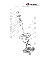
FIG. 11-1 


DISPENSER ASSEM 


Содержание EXS-303

Страница 1: ...1 SEMI AUTOMATIC STRAPPING MACHINE MODEL EXS 303 OPERATION MANUAL 2019 08 19...

Страница 2: ...assification of packaging machines and associated equipment EN 415 8 2008 Safety of packaging machines Part 8 Strapping machines EN ISO 12100 2010 Safety of machinery General principles for design Ris...

Страница 3: ...rating 9 1 7 During Operation 9 1 8 After operating 9 1 9 Signs 10 2 MACHINE INFORMATION 2 1 Areas of Application 11 2 2 Environmental Information 11 2 3 Machine Description 12 2 4 Safety Devices 13 2...

Страница 4: ...4 4 OPERATING THE MACHINE 22 5 ADJUSTMENT 23 6 TROUBLE SHOOTING 25 7 MAINTENANCE 26 8 ELECTRIC WIRING DIAGRAM PART 28 9 PART LIST 33...

Страница 5: ...relevant to accident prevention and environmental protection in addition to the operating instructions For safety reasons long hair must be tied back or otherwise secured garments must be close fitti...

Страница 6: ...s to be stopped and locked immediately In case of any malfunction the machine must be stopped and locked until the defect has been eliminated Generally make sure that nobody is at risk before starting...

Страница 7: ...at regular intervals Tighten any loose connections Check wiring for scorch marks replace scorched wiring and determine and correct the reason for the overheating When working on live equipment ensure...

Страница 8: ...nt of the cord or plug is necessary connect the ground wire to the ground terminal of the plug The wire with green insulation with or without yellow stripes is the grounding wire Check with a qualifie...

Страница 9: ...r 25kg it may be necessary to use lifting aids for handling while package weight over 40kg it s necessary to handle it with conveyor system The size of the package should not be less than 70 mm 20 mm...

Страница 10: ...gns Caution Electric Shock Hazard Caution Hot Surface Caution Moving Parts Can Crush Hand Caution Pinch Point Entanglement Caution Blade Cutting of Fingers or Hand Wear Eye Protection Refer to Operato...

Страница 11: ...d Wet Products Flammable products Explosive products Agri foodstuffs Pharmaceuticals Hazardous products 2 2 Environmental Information The strapping machine shall be installed in the following conditio...

Страница 12: ...o minimize the emission sound pressure level machine is equipped with a timer standby mode that can be adjusted by technician Demolition and Waste Disposal The machine does not contain dangerous compo...

Страница 13: ...equipped with safety devices as Warning labels Live parts are covered Table cover with screw fixed 1 Only Polypropylene strapping can be used in this machine The use of other synthetic Straps can prod...

Страница 14: ...ap jam for example the table top can be unscrewed Observe caution as the machine is still fully functional with the covers removed If machine with safety switch when table top is opened safety switch...

Страница 15: ...60 60 Hz Type of Current AC single phase AC single phase 2 5 2 Technical information STRAP WIDTH 5 15 5mm ONLY ADJUSTMENT STRAP THICKNESS 0 45mm 0 7mm STRAP COIL Coil diameter 200mm 230mm 280mm as opt...

Страница 16: ...ase of problem or when requesting spare parts etc ref 1 2 3 4 This plate also carries electrical technical data for installation of the machine ref a b c d e f g a b c d e f g 1 2 3 4 1 Model 2 Serial...

Страница 17: ...olyester strap secured 3 2 Transportation Unload Machine from Pallet The machine needs to be secured well on wooden pallet The side edge of machine body needs to be sitting on the pallet to make sure...

Страница 18: ...18 3 3 Operation Space Keep the area A and B free for the operator The area A is necessary for operation strapping machine or changing the strap coil...

Страница 19: ...ockwise to decrease tension Feed length adjust VR This adjust VR is to control feeding length for next strap Rotate clockwise to increase feeding length and counter clockwise to decrease feeding lengt...

Страница 20: ...through the strapping head a Rotate nut handle A counter clockwise to remove from dispenser unit take off the dispenser flange and remove old strap coil inside b Remove all adhesive strips or other a...

Страница 21: ...1 Noted Please make sure PP strap is in correct curve down direction to have the PP strap insert into machine in opposite direction it might cause auto threading feed refeed functions not stable A B C...

Страница 22: ...end of strapping sequence the strap end is fed automatically and Feed length adjustment knob is to adjust the strap length g Adjustment JOG This JOG function is for service only it could make machine...

Страница 23: ...between 5mm and 15 5mm strap only adjustment Noted Tool Needed a With three marking as 5mm 9mm 12mm for 15 5mm just pull out the adjust plate to the end Please follow the marking on the adjust plate t...

Страница 24: ...24 b Adjust this guide with strap width with 1mm more and then tight screw to fix the adjustment c Adjust this guide with strap width with 1mm more and then tight screw to fix the adjustment...

Страница 25: ...for higher temperature setting Please adjust Cooling Time VR for longer cooling time setting Please use JOG to check if heater plate s movement is smooth Machine cannot feed Please press RESET button...

Страница 26: ...vice please do switch off the main power on the machine then wait about 5 minutes to cool down the heater plate Weekly Maintenance Use air gun to clean dust from the machine especially following clean...

Страница 27: ...aning and lubrication please do several bundles to check Monthly Maintenance Please take out END GRIPPER UNIT and WELDING CLAMP UNIT to do complete cleaning and lubrication Please clean both sides upp...

Страница 28: ...28 8 ELECTRIC WIRING DIAGRAM PART...

Страница 29: ...29...

Страница 30: ...30...

Страница 31: ...P0305 030000200 P0305 020001000 P0305 020001100 FUSE 3A 6 30mm FUSE SEAT FUSE CAP 1 1 1 S2 S3 P0313 010006800 BUTTON BLACK 2 S1 P0313 010007300 BUTTON BLUE 1 P1 P0309 010013000 MAIN PCB 1 P2 P0315 02...

Страница 32: ...32...

Страница 33: ...33 9 PART LIST...

Страница 34: ...34 FIG 1 1 SEALER SEAT UNIT...

Страница 35: ...05Z SPRING WASHER 5 6 14 P1102 0105AN NUT M5 4 15 P1202 0011500 SEPERATOR ARM SPRING 1 16 P06 0066400 ARM SPACER 4 17 P1202 0011900 WELDING CLAMP SPRING 2 18 P02 0357300 ARM SHAFT 1 19 HOLDING GRIPPER...

Страница 36: ...2 34 P1103 0203Z SPRING WASHER 3 2 35 P1101 0506012AN SCREW M6x12L 1 36 P1103 01062102Z WASHER M6x21x2t 1 37 P1103 0206Z SPRING WASHER 6 1 38 P1101 0304035AZ SCREW M4x35L 4 39 POSITION CAM UNIT 1 40...

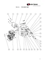
Страница 37: ...37 FIG 2 1 FEED DRIVE UNIT...

Страница 38: ...11 P02 0362500 DRIVEN ROLLER UNIT 1 12 P1106 020000200 MAGNET 2 13 P1101 0203008AZ SCREW M3X8 2 14 P1103 010412N WASHER 4 1 15 P1101 0904008AN SCREW M4x8 1 16 P1101 0906012AN SCREW M6x12 1 17 P01 057...

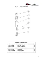
Страница 39: ...END GRIPPER UNIT NO PART NUMBER DESCRIPTION QTY 1 P02 035680A CLAMP SEAT SHORT 1 2 P02 0362900 CAM FOLLOWER UNIT 1 3 P1109 0104018B PIN 4 18 1 4 P02 0357100 END GRIPPER 1 5 P1201 0010200 COMPRESS SPR...

Страница 40: ...MP UNIT NO PART NUMBER DESCRIPTION QTY 1 P02 035700A CLAMP SEAT LONG 1 2 P02 0362900 CAM FOLLOWER UNIT 1 3 P1109 0104018B PIN 4x18 1 4 P02 0357200 CUTTER 1 5 P1201 0010200 COMPRESS SPRING 1 6 P1202 00...

Страница 41: ...NUMBER DESCRIPTION QTY 1 P02 0358000 HOLDING GRIPPER 1 2 P1201 0010200 COMPRESS SPRING 1 3 P02 0362900 CAM FOLLOWER UNIT 1 4 P02 035700A CLAMP SEAT LONG 1 5 P1109 0104018B PIN 4X18 1 6 P1101 0504016A...

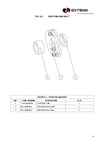
Страница 42: ...42 FIG 6 1 POSITION CAM UNIT FIGURE 6 1 POSITION CAM UNIT NO PART NUMBER DESCRIPTION QTY 1 P02 0362600 POSITION CAM 1 2 P02 0360500 SPACER RING SHORT 1 3 P02 0360400 SPACER RING LONG 1...

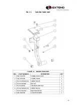
Страница 43: ...UMBER DESCRIPTION QTY 1 P02 0357500 SLIDING TABLE ARM 1 2 P02 0357400 SLIDING TABLE 1 3 P1101 0505025AN SCREW M5X25 1 4 P1102 0105AN NUT M5 1 5 P1103 0205Z SPRING WASHER 5 1 6 P1101 0405012AN SCREW M5...

Страница 44: ...44 FIG 8 1 SEPARATING PLATE UNIT...

Страница 45: ...VX 5 1A2 1 4 P01 0575700 ACTUATOR 1 5 P1104 020635ZZ2 BALL BEARING 635ZZ 1 6 P1103 0205Z SPRING WASHER 5 4 7 P1101 0105012AZ SCREW M5 12 1 8 P1101 0505010AN SCREW M5x10 2 9 P1101 0904008AN SCREW M4x8...

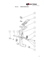
Страница 46: ...46 FIG 9 1 HEATER PLATE UNIT...

Страница 47: ...5 3 P1101 0505012AN SCREW M5 12 1 4 P02 0357600 SEPERATOR ARM 1 5 P1101 0505045AN SCREW M5 45 1 6 P1102 0105AN NUT M5 2 7 P1202 0011700 HEATER PLATE SPRING 1 8 P1104 0310101 BUSHING CB1010 2 9 P01 057...

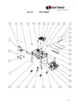
Страница 48: ...48 FIG 10 1 BODY FRAME...

Страница 49: ...AZ SCREW M5 12 4 14 P1103 010510N WASHER 5 10 4 15 P1103 0205Z SPRING WASHER 5 6 16 P01 0579900 ELECTRICAL BOX 1 17 P01 0580100 FRONT TABLE COVER 1 18 P1114 01000020B PLASTIC CAPS 6 19 P01 0585000 ELE...

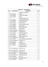
Страница 50: ...50 FIGURE 10 1 BODY FRAME NO PART NUMBER DESCRIPTION QTY 33 P1101 0505016AN SCREW M5 16 1 34 P1101 0405012AN SCREW M5 12 4 35 P1101 0404008AN SCREW M4 8 3 36 P1101 0104006AZ SCREW M4 6 10...

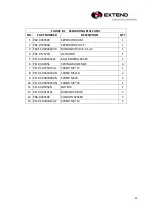
Страница 51: ...51 FIG 11 1 DISPENSER ASSEM...

Страница 52: ...BELT PLATE REAR 1 12 P01 057820A BELT FIXER 1 13 P01 058420A BELT ADJUST PLATE 1 14 P1101 0508030AN SCREW M8 30 1 15 P1202 0012500 BRAKE SPRING 1 16 P1101 0506045AZ SCREW M6 45 1 17 P0902 0001400 V BE...

Страница 53: ...53 FIG 12 1 DISPENSER UNIT...

Страница 54: ...6AZ SCREW M6 4 6 P06 0058100 DISPENSER HANDLE 2 7 P1103 0206Z SPRING WASHER 6 4 8 P1101 0904018AN SCREW M4 18 6 9 P1103 01040801Z WASHER M4 8 1t 6 10 P1102 0104AN NUT M4 6 11 P1103 010612N WASHER 6 12...

Отзывы: