Exodraft EBC10 Скачать руководство пользователя страница 13

1.7.1 

Overview of the service menu

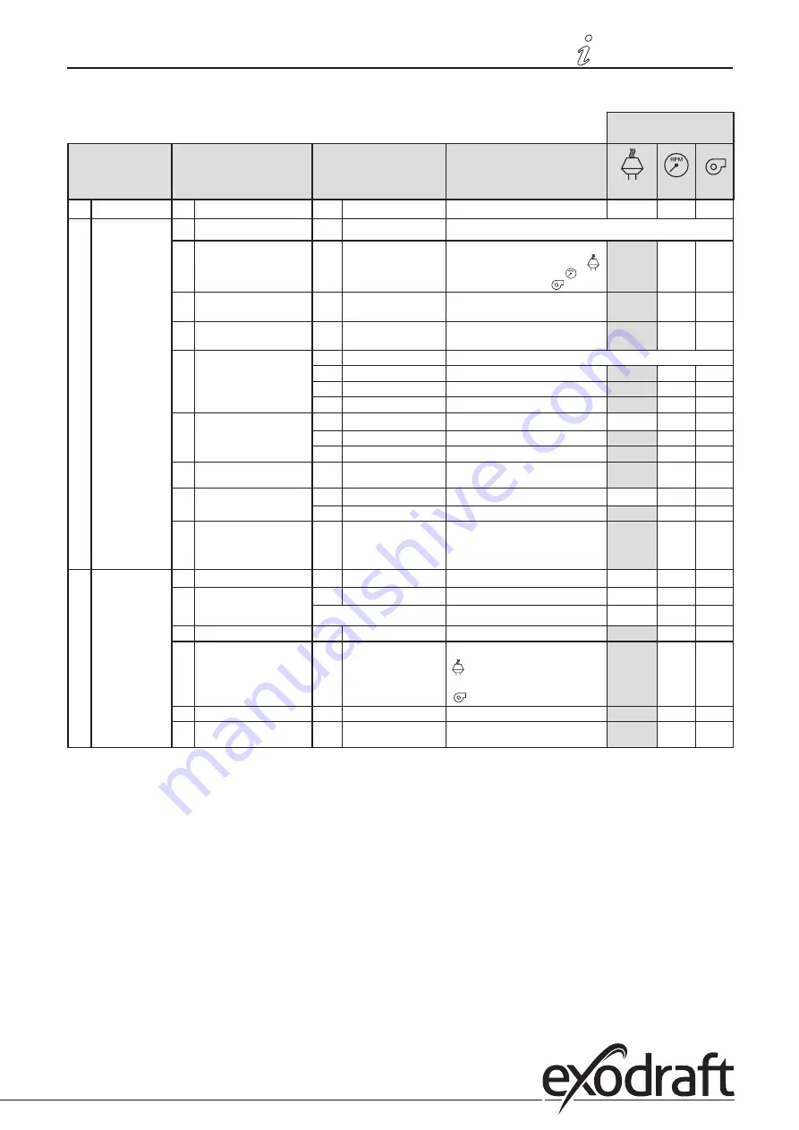
The service menu is built up in four levels:

Base settings for the 

three applications

Menu level 1

Menu level 2

Menu level 3

Function

Default

0

Exit Service menu

Return to operation screen

1

Operation settings

10

Exit operation settings

11

Operating mode

Setting of control/operating function
1 = Pressure-controlled regulation 

2 = 2-stage speed regulation 

3 = Supply air regulation 

1

12

°C/°F

Select measuring unit for temperature

1 = °C, 2 = °F

1 (°C)

1 (°C)

1 (°C)

13

Pa/inWC

Measuring unit for pressure: 

1 = Pa, 2 = inWC

1 (Pa)

1 (Pa)

1 (Pa)

14

Software versions

140

Exit 

141

Controller version

View Controller software version

x.xx

x.xx

x.xx

142

Safety version

View Safety software version

x.xx

x.xx

x.xx

143

Display version

View Display software version

x.xx

x.xx

x.xx

15

Select XTP measurement 

range

150

Exit 

151

Set Low XTP value

from -500 Pa to 0 Pa

0 Pa

N/A

0 Pa

152

Set High XTP value

from 0 Pa to 500 Pa

150 Pa

N/A

150 Pa

16

Positive/negative pressure

1 = negative pressure

2 = positive pressure

1

N/A

1

17

OEM functions

170

Exit

171

Cooker function

Switch Cooker function ON and OFF

N/A

OFF

N/A

18

Reset to defaults

Reset to defaults. If you select “YES”, a 

10-second countdown will start, 

during which you can cancel your 

choice by pressing any button.

NO

NO

NO

2

Alarm

20

Exit Alarm

21

Alarm Log

210

Exit

211-219

The 9 most recent alarms

22

Reset alarm log

Resets alarm log

NO

NO

NO

23

Flow Alarm limit

Set Flow Alarm limit in %:

50-80 % 

(Alarm when pressure is below xx% )

100-300 % 

(Alarm when pressure is above xx% )

64 %

N/A

300 %

24

Flow Alarm delay

Set Flow Alarm delay, 10–60 s

15 s

15 s

15 s

25

Reset auto / manual

1 = automatic, 2 = manual

1  

(Auto)

(Auto)

(Auto)

3120049-EBC10-UK

Product information • 

13

Product information • 

13

Содержание EBC10

Страница 1: ...Instructions for fitting installation and operation UK EBC10 EBC10 ALARM RESET OK Read and save these instructions...

Страница 2: ...6 2 4 1 Single boiler application 17 2 4 2 Single boiler application with potential free contact in boiler 18 2 4 3 Single boiler application with extra fail safe protection using PDS 19 2 4 4 Solid f...

Страница 3: ...ions contact the supplier at the address or telephone number listed on the back of the manual Before servicing or cleaning the unit switch off at service panel and lock service panel to prevent power...

Страница 4: ...section 2 Pressure controlled regulation of exodraft fans factory set Read sections 3 5 Section 2 Pressure controlled regulation of exodraft chimney fans default The EBC10 ensures and monitors consta...

Страница 5: ...oor installation E 2 m silicone hose 2000335 Supplies the pressure transducer XTP with reference pressure from the measuring probe or from outdoors Instructions 3120049 Instructions for fitting instal...

Страница 6: ...from being formed The EBC10 should be mounted in a way that protects it against rain snow Note Special aspects if you require positive pressure in the chimney boiler room Connect the hose to the posit...

Страница 7: ...keep water out If the pressure transducer is positioned in a place where insects have access to the free end fitting a sinter filter is recommended 1 4 Layout of the user interface 1 4 1 Panel EBC10...

Страница 8: ...A AC3 red the relay is open 11 12 BOILER 1 IN 18 230VDC VAC green the input is active 13 14 BURNER 1 OUT 250VAC 4A AC3 green the relay is connected 15 16 BOILER 2 IN Not active 17 18 BURNER 2 OUT Not...

Страница 9: ...ney fan 7 Symbol for pressure controlled regulation of exodraft chimney fan 8 Symbol for pressure controlled regulation of exodraft supply air fan 9 Symbol indicating PDS error PDS check flashing 10 O...

Страница 10: ...by qualified technical staff Layout of the user interface The user interface is operated through four buttons with the following functions Button Function Activate the user menu Edit and save setting...

Страница 11: ...lays the actual pressure in this example 30 Pa 2 Briefly press to enter the user menu 3 Press Press and until the required pressure appears in the lower display 4 Press OK to confirm the setting 5 To...

Страница 12: ...set point for this menu being shown in the lower display pos 13 on page 9 Menus whose last digit is 0 are exit menus These are used to navigate one level back To do so press OK To activate the editin...

Страница 13: ...ion x xx x xx x xx 15 Select XTP measurement range 150 Exit 151 Set Low XTP value from 500 Pa to 0 Pa 0 Pa N A 0 Pa 152 Set High XTP value from 0 Pa to 500 Pa 150 Pa N A 150 Pa 16 Positive negative pr...

Страница 14: ...Set proportional amplification 0 2 to 5 2 2 N A 1 2 352 Integration time Ti Set integration time from 1 to 30 s 5 N A 3 353 Differential time Td Set differential time from 1 to 30 s 1 N A 5 354 Sample...

Страница 15: ...to go to menu 10 3 Press to go to menu 11 Press OK 4 Press until the symbol and number for the opera ting function you require is displayed The three opera ting functions are 1 Pressure controlled reg...

Страница 16: ...outputs are linked to light emitting diodes for the monitoring and service of the system 1 4 2 Light emitting diodes and terminal board page 8 2 3 Electrical connection This work must be performed by...

Страница 17: ...the boiler Connect the burner start signal L to terminal 11 Connect the neutral wire to terminal 12 The start signal for the burner is sent from terminal 14 Loop terminals 11 and 13 Connect the chimn...

Страница 18: ...to terminals 1 3 Connection to the boiler Connect the potential free contact to terminals 11 19 Loop terminals 12 20 Connect the burner start signal to terminals 13 14 Connect the chimney fan to term...

Страница 19: ...ge to terminals 1 3 Connect the burner startsignal to terminal 12 The start signal to the burner comes back on terminal 14 Connect the burner start signal to terminal 11 Loop terminals 12 and 13 Conne...

Страница 20: ...iler Connect the burner start signal L to terminal 11 Connect the neutral wire to terminal 12 Loop terminals 11 and 13 The start signal from the burner comes from terminal 14 Connect the ventilator to...

Страница 21: ...enu items 1 4 in the same way as shown in the example in page 11 To operate menu items 1 4 use the buttons as follows Step Press To 1 OK Activate the user menu 2 and Go to the menu item you wish to ed...

Страница 22: ...om step 1 4 Check that the monitoring system shuts off the boiler To simulate an error situation disconnect the hose from the pressure transducer XTP Burner is switched off diode switches off and the...

Страница 23: ...reset In the event of an alarm undertake the following procedure Step Action 1 Go to menu 4 menu 5 for operating function 2 to display the current alarm 2 Check the alarm overview next page to identif...

Страница 24: ...erminals 26 28 Check the connections to terminals 26 28 the setting in menu 31 2 the loop between terminals 26 and 28 If XTP is connected power off on the unit If error persist contact dealer defectiv...

Страница 25: ...LEDs Remove the front panel This work must be performed by a qualified electrical engineer 3 2 2 Communication error If the display shows three horizontal lines in the lowest display box Press RESET a...

Страница 26: ...igital inputs BOILER 1 IN 18 to 230 VAC VDC Pressure sensor input XTP IN 0 to 10 VDC 20 mA Pressure switch input PDS IN 24 VDC 20 mA Temperature sensor TEMP IN 30 C to 500 C Outputs Digital output rel...

Страница 27: ...iften uit de hieronder genoemde normen en standaards som omfattas av denna deklaration verensst mmer med f ljande standarder jota t m selvitys koskee on seuraavien standardien mukainen sem eru me tali...

Страница 28: ...info exodraft se www exodraft se NO exodraft a s Storgaten 88 NO 3060 Svelvik Tel 47 3329 7062 Fax 47 3378 4110 info exodraft no www exodraft no UK exodraft Ltd 10 Crestway Tarleton GB Preston PR4 6B...

Отзывы: