Maintenance
Adjustments
Note:
Disengage PTO, shut off engine, wait for
all moving parts to stop, engage parking brake, and
remove key before servicing, cleaning, or making any
adjustments to the unit.
CAUTION
Raising the mower for service or maintenance
relying solely on mechanical or hydraulic
jacks could be dangerous. The mechanical or
hydraulic jacks may not be enough support or
may malfunction allowing the unit to fall, which
could cause injury.
Do Not rely solely on mechanical or hydraulic
jacks for support. Use adequate jack stands or
equivalent support.
Deck Leveling
Note:
Small adjustments can be accomplished by
increasing the tire pressure in the tire on the low side.
1. Park the machine on a level surface and disengage
the blade control switch.
2. Stop engine, wait for all moving parts to stop, and
remove key. Engage parking brake.
3. Check the air pressure in the drive tires. If needed,
adjust to the recommended inflation; refer to
Checking the Tire Pressure
in Drive System
Maintenance section.
4. Set the height of cut lever to the 3 inch (7.6 cm)
position.
5. Raise the discharge deflector.
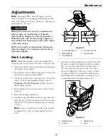
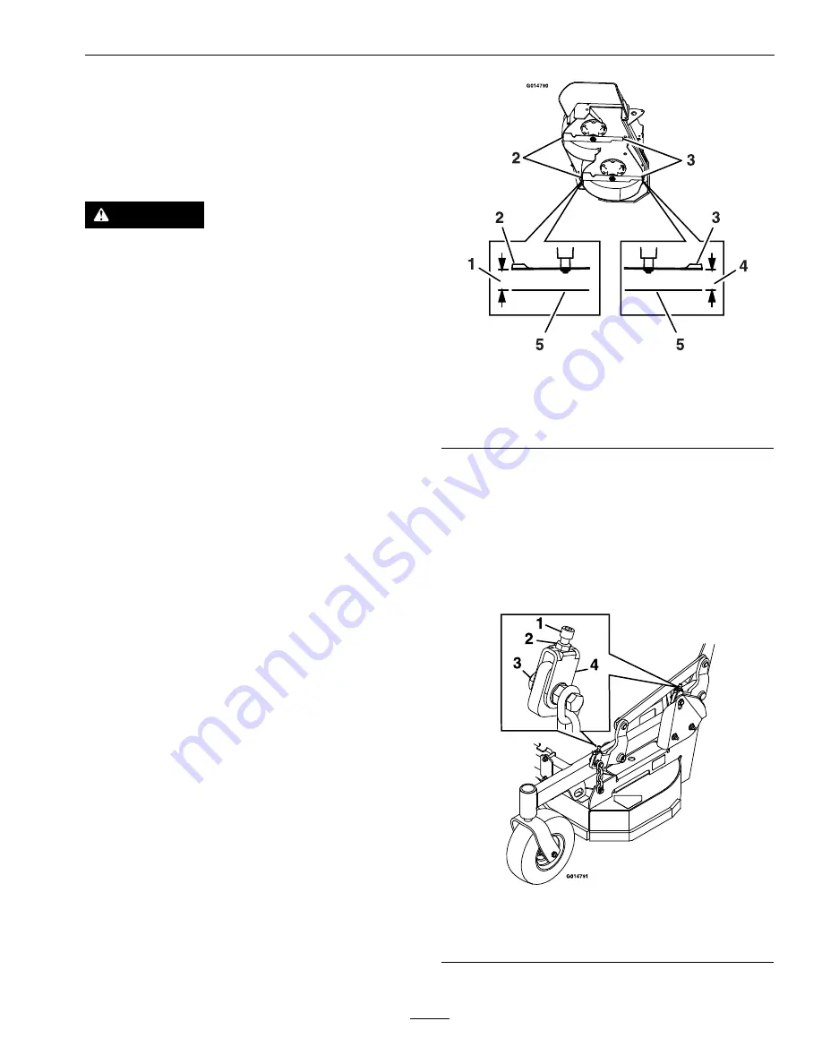
6. Carefully rotate the blades front to rear. Measure
from the tip of the front blade to the level surface
(Figure 22). The blades should measure 3 inches
(7.6 cm).
Note:
In most conditions, the back tips should
be adjusted 1/4 inch (6.4 mm) higher than the
front.
Figure 22
1.
3 1/4 inches (8.3 cm)
4.
3 inches (7.6 cm)
2.
Back blade tip
5.
Level surface
3.
Front blade tip
7. Use the fine tune adjustments on the front deck
lift arms to adjust the height of the front blade
tips. Loosen the whizlock nut on the side of
the yoke and the jam nut on top. Fine tune
the screw adjuster by turning it to get 3 inches
(7.6 mm) height. To increase the height, turn
the adjuster screw clockwise; to decrease, turn
counterclockwise (see Figure Figure 23).
Figure 23
1.
Adjuster screw
3.
Whizlock nut
2.
Jam nut
4.
Yoke
35
Содержание VANTAGE S Series
Страница 1: ...VANTAGE S SERIES 36 INCH MODELS For Serial Nos 316 000 000 Higher Part No 4502 635 Rev A ...
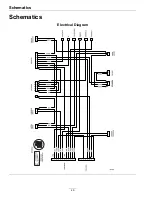
Страница 46: ...Schematics Schematics Electrical Diagram 46 ...
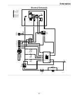
Страница 47: ...Schematics Electrical Schematic 47 ...
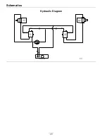
Страница 48: ...Schematics Hydraulic Diagram 48 ...
Страница 50: ...50 ...

