Maintenance
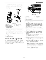
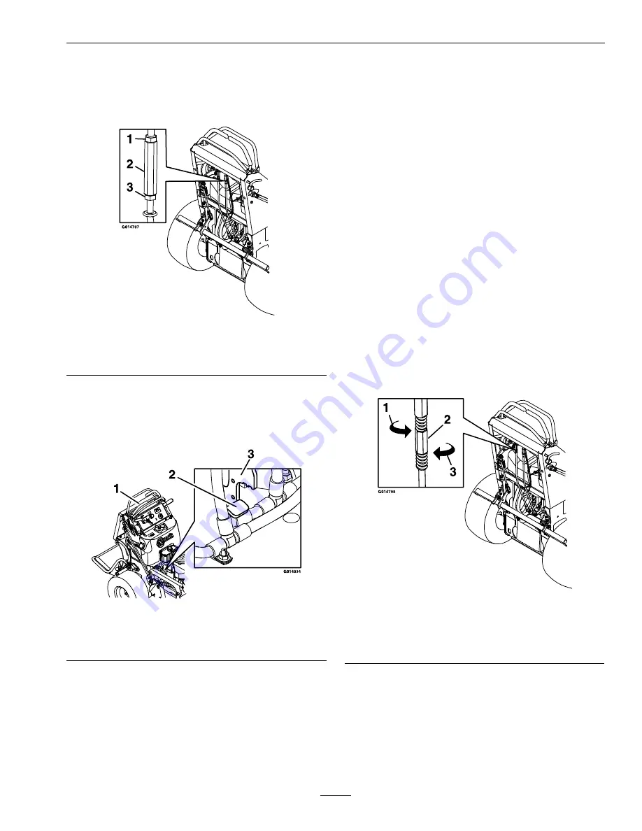
machine — see Figure 31). Rotate the turnbuckle
counterclockwise (as viewed from the top of the
machine) until there is a gap between the control
lever and the front reference/speed control bar.
Figure 31
1.
Lock nut
3.
Lock nut (LH thread)
2.
Turnbuckle
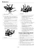
7. With the RH control lever all the way forward,
make sure the RH pump arm bottoms out on the
forward stop, located by the hydraulic hoses, as
shown in Figure 32.
Figure 32
1.
RH control lever
3.
RH pump arm
2.
Forward stop
8. Holding the RH control lever forward, rotate the
turnbuckle clockwise until there is a minimal gap
or contact between the RH control lever and the
front reference/speed control bar.
9. Tighten the jam nuts.
10. Reinstall the rear cushion.
Motion Control Tracking
Adjustment
If the machine travels or pulls to one side when the
motion control levers are in the full forward position,
adjust the tracking.
1. Push both control levers forward the same
distance.
2. Check if the machine pulls to one side. If it does,
stop the machine and set the parking brake.
3. Release the rear cushion from the rear of the
machine.
4. Place the front reference/speed control bar in
the maximum forward position. See
Adjusting
the Front Reference/Speed Control Bar
in
Operation.
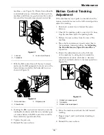
5. Rotate the adjustment rod on the LH side
of the machine. Looking down towards the
adjustment rod, rotate clockwise to decrease
speed or counterclockwise to increase speed (see
Figure 33).
Figure 33
1.
Rotate to increase speed
2.
Turnbuckle
3.
Rotate to decrease speed
6. Drive the machine and check the full forward
tracking.
7. Repeat steps 5 and 6 until desired tracking is
obtained.
8. Reinstall the rear cushion.
39
Содержание VANTAGE S Series
Страница 1: ...VANTAGE S SERIES 36 INCH MODELS For Serial Nos 316 000 000 Higher Part No 4502 635 Rev A ...
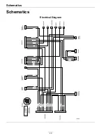
Страница 46: ...Schematics Schematics Electrical Diagram 46 ...
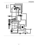
Страница 47: ...Schematics Electrical Schematic 47 ...
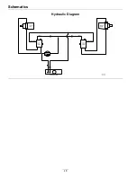
Страница 48: ...Schematics Hydraulic Diagram 48 ...
Страница 50: ...50 ...

