Exmark ULTRA VAC LAZER Z LHPUV4448 Скачать руководство пользователя страница 9

109-3195 Rev. C 

Page 9 of 9 

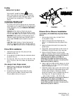
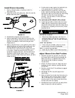
Install Blower Assembly


1.  Remove the belt guide on the blower (Item 11). 

(See Figure 12) 

2.  Install the belt (from the Drive Kit – Item 24) onto the 

Blower Assembly (Item 11) as shown. 


FIGURE 12 

3.  Reinstall the belt guide removed in step 1. 

4.  Remove Discharge Chute (Item 20) by pulling the 

hairpin (Item 19) and chute pivot pin (Item 18) (from 
the Drive Kit installed in section 

Discharge Chute 

Replacement.

). 

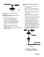
5.  Remove the Belt Cover on the right side of the deck. 

Install the Blower by inserting the mounting pin into 
the tube welded to the rear corner of the deck.  
Pivot the blower until the front pin engages the slot 
in the deck.  Adjust the position of the front pin if 
necessary to engage the slot.  Use the latch to lock 
the blower in this position (See Figure 13).  Adjust 
tension on latch to draw blower up to deck, yet allow 
release by hand. 


FIGURE 13 

6.  Pull the idler release handle and install the belt 

in the upper groove of the deck sheave. 

7.  Install the Belt Cover (Item 25) using the two 

knobs. Install the discharge tube assembly by 
slipping the upper end into the hood, then sliding 
the lower end over the blower discharge 
opening.  Use the latches  to retain the lower 
end to the blower. 

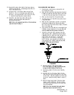
For units above SN 600,000 (Triton deck):


8.  Adjust dog leg baffle to match Ultra Vac blower 

intake opening.  Adjusting too wide may allow 
objects to be thrown from under the mower deck 
at high speed.  Adjusting too narrow may cause 
plugging issues. 

WARNING


POTENTIAL HAZARD 

  If the blower intake opening is not correct it 

will allow objects to be thrown in operator’s or 
bystander’s direction.  Also, contact with blade 
could occur. 

WHAT CAN HAPPEN 

  Thrown objects or blade contact can cause 

serious injury or kill you or bystanders. 

HOW TO AVOID THE HAZARD 

  Adjust dog leg baffle to match intake opening. 


Adjust Blower Drive Belt Position 

1.  Read the operator’s manual for the Ultra Vac 

and mower before performing this adjustment.  
Make sure that you understand the controls, 
their locations their functions and safety 
requirements. 

2.  Ensure the blower, belt cover, bags, tube and 

hood are in good condition, properly attached 
and latched. 

3.  Run the unit with the PTO and blower engaged 

for two minutes. 

4.  Disengage the PTO, stop the engine and 

remove key. 

5.  Remove the belt cover and check to make sure 

that the belt is riding near the center of the flat 
idler on the idler arm.  If the belt is not riding 
near the center of the idler, remove the blower, 
and bend the idler arm slightly.   

6.  Reinstall the blower and belt cover and perform 

steps 3-5 again to verify belt position. 


Содержание ULTRA VAC LAZER Z LHPUV4448

Страница 1: ...4 103 5629 LHPUV4650 46 Deck Drive Kit Front Weight Kit All Serial Numbers 109 1013 103 5629 50 Deck Drive Kit Front Weight Kit All Serial Numbers 109 1014 103 5629 LHPUV5256 52 Deck Drive Kit Front Weight Kit All Serial Numbers 109 1185 103 5629 Front weight Kit 103 5629 is required on any unit with a 2 post ROPS installed 56 Deck Drive Kit Front Weight Kit All Serial Numbers 109 1015 103 5629 LA...

Страница 2: ...ex Head Screw 4 1 Hood Assembly 5 2 Bag Assembly 6 1 Upper Tube 7 1 Lower Tube Assembly 8 3 10 24 X 75 Hex Head Screw 9 3 10 Flat Washer Key Qty Description 10 3 10 24 Nyloc Nut 11 1 Blower Assembly 12 Ref Rear Weight 52 and 56 units 13 Ref Spacer 52 only 14 8 5 16 18 X 1 75 Hex Head Screw 15 4 5 16 18 Whizlock Nut 16 2 Clevis Pin 17 2 Hair Pin FIGURE 1 ...

Страница 3: ...1 Belt Blower 25 1 Cover Belt 26 1 5 16 18 X 62 Hex Head Screw 27 1 Plug Ultra Vac Weight Kit units with 2 post ROPS only Key Qty Description 28 1 Asm Weight 29 2 Plate Weight Mounting 30 4 5 16 18 x 1 Hex Head Screw 30 4 5 16 18 x 1 1 2 Hex Head Screw 31 1 Flat Washer 5 8 32 2 Carriage bolt 5 16 18 x 1 00 33 1 Strap 34 2 Pin Hair 35 4 5 16 Washer 36 4 5 16 18 Whizlock 46 50 and 56 Triton units Al...

Страница 4: ...ve the discharge chute 2 Reinstall the discharge chute Item 20 using the chute pivot pin Item 18 and hairpin Item 19 provided as shown in Figure 3 FIGURE 3 Blower Drive Sheave Installation Units Below 510 000 Without Splined Blade Driver 1 Stop engine remove key and wait for all moving parts to stop 2 Remove the right side belt shield and the 5 16 x 3 1 4 bolt that secures the shield to the deck 3...

Страница 5: ...ht side belt shield and the 5 16 x 3 1 4 bolt that secures the shield to the deck 3 Remove the blade from the right spindle 4 Insert special tool 109 2979 into splined end of spindle shaft 5 Remove the right sheave nut spring disk washer and drive sheave from the spindle shaft 6 Use special tool 109 2979 to hold spindle from rotating keep hardware for re use Do not use the blade bolt to prevent ro...

Страница 6: ... the spindle shaft Do not remove the blade drive sheave Retain the nut for later use 6 Use special tool 109 2979 to hold spindle from rotating keep hardware for re use Do not use the blade bolt to prevent rotation 7 Install the Ultra Vac drive sheave onto the right spindle shaft Install the washer that is supplied with the Ultra Vac drive kit Item 31 and nut removed in step 1 Torque the sheave nut...

Страница 7: ...pan 3 Permanently mount the weight mounting plate to the front panel of the floor pan using 4 5 16 18 x 1 50 hex head screws 4 washers 4 whizlock nuts and the mounting strap Items 30 33 35 36 4 Hook the weight plate assembly Item 28 over the top of the weight mounting plates and secure with two hairpins Item 34 FIGURE 8 Install Hood Assembly and Bags 44 46 48 and 50 inch units 1 Remove the 12 bolt...

Страница 8: ...hopper seal Item 4 push in then pull out so that seal is extended outward 3 Align dimple on upper tube Item 6 with end of hopper seal and position vertically between the two screws Item 4 as shown in Figure 10 FIGURE 10 4 Set deck in lowest cutting position 5 Slide lower tube Item 7 onto blower Item 11 and latch make sure that upper tube does not move out of alignment 6 Drill 7 32 holes in lower t...

Страница 9: ...ower end to the blower For units above SN 600 000 Triton deck 8 Adjust dog leg baffle to match Ultra Vac blower intake opening Adjusting too wide may allow objects to be thrown from under the mower deck at high speed Adjusting too narrow may cause plugging issues WARNING POTENTIAL HAZARD If the blower intake opening is not correct it will allow objects to be thrown in operator s or bystander s dir...

Отзывы: