

109-3195 Rev. C
Page 5 of 9
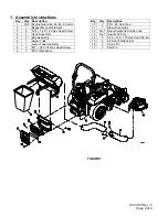
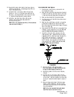
FIGURE 4
Check blade bolt torque after completing this
installation:
For units with a 5/8-18 x2 3/4 blade bolt, torque to
115-120 ft-lbs (156-163 N-m)
8. Reinstall the deck drive belt in the lower
groove of the double sheave. Install plug
(Item 27) into bore of double sheave.
9. Install 5/16-18 x .62 screw (Item 26) into hole
that 5/16 – 18 x 3 ¼ bolt was removed from
on the deck. Use the whizlock nut removed in
step 2). Install bolt with head to inside of
deck.
10. Install the new belt cover (Item 25) secure
with the two belt shield knobs (Item 22) as
shown in Figure 2.
NOTE: Do not re-install the 5/16 x 3 1/4 bolt that was
removed in step 2.
Units Below 600,000 With Splined Blade
Driver
1. Stop engine, remove key, and wait for all
moving parts to stop.
2. Remove the right side belt shield and the
5/16 x 3 1/4 bolt that secures the shield to the
deck.
3. Remove the blade from the right spindle.
4. Insert special tool 109-2979 into splined end
of spindle shaft.
5. Remove the right sheave nut, spring disk
washer, and drive sheave from the spindle
shaft.
6. Use special tool 109-2979 to hold spindle from
rotating – keep hardware for re-use. Do not
use the blade bolt to prevent rotation.
7. Apply a light coat of Mobil HTS grease (or
food grade antiseize) to the top portion of the
spindle shaft where the sheave mounts.
8. Install the double sheave (Item 23) onto the
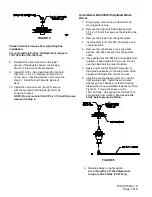
right spindle shaft. Install the spring disk
washer and nut. Make sure that the spring
disk washer cone is installed towards nut (See
Figure 5). Torque the sheave nut to
140-145 ft-lbs. Use special tool 109-2979 to
hold spindle from rotating.
Do not use the
blade bolt to prevent rotation.
FIGURE 5
9. Reinstall blade on right spindle.
For units with a 1/2-20x2 blade bolt,
torque to 50-60 ft-lbs (75-81 N-m)


