

109-3195 Rev. C
Page 4 of 9
Safety
Safety Alert Symbol
This SAFETY ALERT SYMBOL
is used
both in this instruction sheet and on the machine
to identify important safety messages which must
be followed to avoid accidents. This symbol
means:
ATTENTION! BECOME ALERT!
YOUR SAFETY IS INVOLVED!
The safety alert symbol appears above information
which alerts you to unsafe actions or situations and
will be followed by the word
DANGER
,
WARNING
,
or
CAUTION.
DANGER
: White lettering / Red background.
Indicates an imminently hazardous situation which,
if not avoided,
WILL
result in death or serious injury.
WARNING
: Black lettering / Orange background.
Indicates a potentially hazardous situation which, if
not avoided,
COULD
result in death or serious
injury.
CAUTION
: Black lettering / Yellow background.
Indicates a potentially hazardous situation which, if
not avoided,
MAY
result in minor or moderate injury.
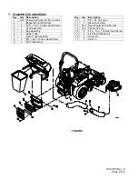
Drive Kit Installation
1. Identify the part number of the drive kit to be
installed on the unit.
2. For weight kit 103-5629 follow the instruction sheet
provided in the kit.
3. For drive kits, 103-1314, 103-1315, 109-1013, 109-
1014, 109-1015, 109-1185 follow the instructions
below:
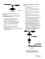
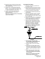
Discharge Chute Replacement
1. Remove two (2) capscrews connecting the
discharge chute to the deck. Remove the
discharge chute.
2. Reinstall the discharge chute (Item 20) using
the chute pivot pin (Item 18) and hairpin (Item
19) provided as shown in Figure 3.
FIGURE 3
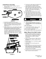
Blower Drive Sheave Installation
Units Below 510,000 Without Splined Blade
Driver
1. Stop engine, remove key, and wait for all
moving parts to stop.
2. Remove the right side belt shield and the
5/16 x 3 1/4 bolt that secures the shield to the
deck.
3. Remove the deck drive belt from around the
right sheave.
4. Support the right mower blade so that it will not
fall off when the right sheave nut is removed.
5. Remove the right sheave nut, spring disk
washer, and drive sheave from the spindle shaft.
NOTE: Block the blade rotation with a block of
wood between the blade and baffles as
indicated in the blade service section of the
Lazer Z HP operator’s manual. Do not use the
blade bolt to prevent rotation.
6. Apply a light coat of Mobil HTS grease (or a food
grade antisieze) to the top portion of the spindle
where the sheave mounts.
7. Install the double sheave (Item 23) onto the right
spindle shaft. Install the spring disk washer and
nut removed in Step 5). Make sure that the
spring disk washer cone is installed towards nut
(See Figure 4). Torque the sheave nut to:
3/4 -16 nut (1 ¼ Hex) – 140-145 ft. lbs.
NOTE: Block the blade rotation with a block of
wood between the blade and baffles as
indicated in the blade service section of the
Lazer Z HP operator’s manual. Do not use the
blade bolt to prevent rotation.
18
20
19


