


Maintenance
spacer nuts to the axle. Remove the axle (with
the other spacer nut still assembled to it) from
the wheel assembly.
5. Pry out seals, and inspect bearings for wear or
damage and replace if necessary.
6. Pack the bearings with a NGLI grade #1
multi-purpose grease.
7. Insert one bearing, one new seal into the wheel.
Note:
Seals (Exmark P/N 103-0063) must be
replaced.
8. If the axle assembly has had both spacer nuts
removed (or broken loose), apply a thread locking
adhesive to one spacer nut and thread onto the
axle with the wrench flats facing outward. Do
Not thread spacer nut all of the way onto the end
of the axle. Leave approximately 1/8 inch (3 mm)
from the outer surface of the spacer nut to the
end of the axle inside the nut.
9. Insert the assembled nut and axle into the wheel
on the side of the wheel with the new seal and
bearing.
10. With the open end of the wheel facing up, fill
the area inside the wheel around the axle full of
NGLI grade #1 multi-purpose grease.
11. Insert the second bearing and new seal into the
wheel.
12. Apply a thread locking adhesive to the 2nd spacer
nut and thread onto the axle with the wrench flats
facing outward.
13. Torque the nut to 75-80 in-lb (8-9 N-m), loosen,
then re-torque to 20-25 in-lb (2-3 N-m). Make
sure axle does not extend beyond either nut.
14. Reinstall the seal guards over the wheel hub and
insert wheel into caster fork. Reinstall caster bolt
and tighten nut fully.
Important:
To prevent seal and bearing damage,
check the bearing adjustment often. Spin the
caster tire. The tire should not spin freely
(more than 1 or 2 revolutions) or have any side
play. If the wheel spins freely, adjust torque on
spacer nut until there is a slight amount of drag.
Reapply thread locking adhesive.
Remove Engine Shrouds and
Clean Cooling Fins
Service Interval: Every 80 hours
1. Stop engine, wait for all moving parts to stop, and
remove key. Engage parking brake.
2. Remove cooling shrouds from engine and clean
cooling fins. Also clean dust, dirt, and oil from
external surfaces of engine which can cause
improper cooling.
3. Make sure cooling shrouds are properly
reinstalled. Operating the engine without
cooling shrouds will cause engine damage due to
overheating.
Check Spark Plugs
Service Interval: Every 160 hours
Remove spark plugs, check condition and reset gaps,
or replace with new plugs. See Engine Owner’s
Manual.
Change Fuel Filter
Service Interval: As required
A fuel filter is installed between the fuel tank and the
engine. Replace when necessary.
For Kohler EFI Units:
WARNING
Fuel system components are under high
pressure. The use of improper components can
result in system failure, gasoline leakage and
possible explosion.
Use only approved fuel lines and fuel filters for
high pressure systems.
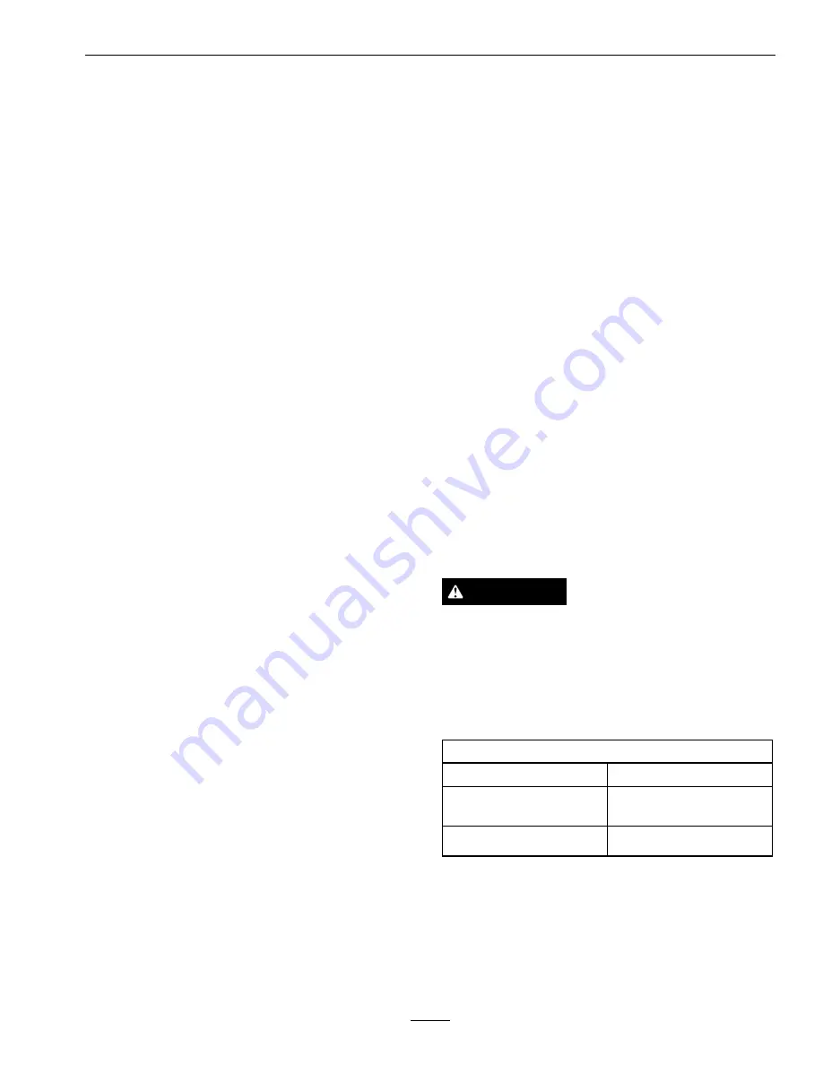
Replacement Filters
Kohler
Kohler
P/N 24 050 13
Kawasaki
Kawasaki
P/N 49019-7005
Kohler EFI
Kohler
P/N 25 050 42
Note:
It is important to reinstall the fuel line hoses
and secure with plastic ties the same as they were
originally installed at the factory to keep the fuel line
away from components that could cause fuel line
damage.
29
Содержание TURF TRACER X-SERIES
Страница 1: ...TURF TRACER X SERIES For Serial Nos 920 000 Higher Part No 4500 699 Rev A ...
Страница 11: ...Safety 103 2242 103 2243 103 4935 103 2432 116 0404 11 ...
Страница 12: ...Safety 116 4296 EFI Units Only 1 Fast 2 Slow 117 2718 12 ...
Страница 38: ...Schematics Schematics Electrical Diagram All units except Kohler EFI 38 ...
Страница 39: ...Schematics Electrical Diagram Kohler EFI 39 ...
Страница 40: ...Schematics Electrical Logic Schematic All units except Kohler EFI 40 ...
Страница 41: ...Schematics Electrical Logic Schematic Kohler EFI 41 ...
Страница 42: ...Schematics Hydraulic Diagram 42 ...
Страница 44: ...Notes 44 ...
Страница 45: ...Service Record Date Description of Work Done Service Done By 45 ...
Страница 46: ...46 ...


