


Maintenance
CAUTION
Corrosion or loose connections can cause
unwanted electrical voltage spikes at anytime
during the jump starting procedure.
Do Not attempt to jump start with loose or
corroded battery terminals or damage to the
engine or EFI may occur.
DANGER
Jump starting a weak battery that is cracked,
frozen, has low electrolyte level, or an
open/shorted battery cell, can cause an
explosion resulting in serious personal injury.
Do Not jump start a weak battery if these
conditions exist.
2. Make sure the booster is a good and fully charged
lead acid battery at 12.6 volts or greater. Use
properly sized jumper cables (4 to 6 AWG) with
short lengths to reduce voltage drop between
systems. Make sure the cables are color coded or
labeled for the correct polarity.
CAUTION
Connecting the jumper cables incorrectly
(wrong polarity) can immediately damage
the EFI system.
Be certain of battery terminal polarity and
jumper cable polarity when hooking up
batteries.
Note:
The following instructions are adapted
from the SAE J1494 Rev. Dec. 2001 – Battery
Booster Cables – Surface Vehicle Recommended
Practice (SAE – Society of Automotive
Engineers).
WARNING
Batteries contain acid and produce explosive
gases.
•
Shield the eyes and face from the batteries
at all times.
•
Do Not lean over the batteries.
Note:
Be sure the vent caps are tight and level.
Place a damp cloth, if available, over any vent
caps on both batteries. Be sure the vehicles do
not touch and that both electrical systems are
off and at the same rated system voltage. These
instructions are for negative ground systems only.
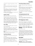
3. Connect the positive (+) cable to the positive (+)
terminal of the discharged battery that is wired to
the starter or solenoid as shown in Figure 10.
Figure 10
1.
Positive (+) cable on discharged battery
2.
Positive (+) cable on booster battery
3.
Negative (–) cable on the booster battery
4.
Negative (–) cable on the engine block
5.
Booster battery
6.
Discharged battery
7.
Engine block
4. Connect the other end of the positive cable to the
positive terminal of the booster battery.
5. Connect the black negative (–) cable to the other
terminal (negative) of the booster battery.
6. MAKE THE FINAL CONNECTION ON
THE ENGINE BLOCK OF THE STALLED
VEHICLE (NOT TO THE NEGATIVE POST)
AWAY FROM THE BATTERY. STAND BACK.
7. Start the vehicle and remove the cables in the
reverse order of connection (the engine block
(black) connection is the first to disconnect).
Check Mower Blades
Service Interval: Before each use or daily
1. Stop engine, wait for all moving parts to stop, and
remove key. Engage parking brake.
2. Lift deck and secure in raised position as stated
in the
Clean Grass Build-Up Under Deck
procedure.
3. Inspect blades and sharpen or replace as required.
4. Reinstall blades (if they were removed) in the
following order:
25
Содержание TURF TRACER X-SERIES
Страница 1: ...TURF TRACER X SERIES For Serial Nos 920 000 Higher Part No 4500 699 Rev A ...
Страница 11: ...Safety 103 2242 103 2243 103 4935 103 2432 116 0404 11 ...
Страница 12: ...Safety 116 4296 EFI Units Only 1 Fast 2 Slow 117 2718 12 ...
Страница 38: ...Schematics Schematics Electrical Diagram All units except Kohler EFI 38 ...
Страница 39: ...Schematics Electrical Diagram Kohler EFI 39 ...
Страница 40: ...Schematics Electrical Logic Schematic All units except Kohler EFI 40 ...
Страница 41: ...Schematics Electrical Logic Schematic Kohler EFI 41 ...
Страница 42: ...Schematics Hydraulic Diagram 42 ...
Страница 44: ...Notes 44 ...
Страница 45: ...Service Record Date Description of Work Done Service Done By 45 ...
Страница 46: ...46 ...


