Operation
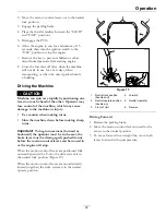
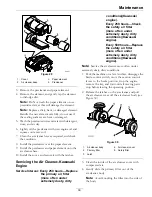
the machine has to be pushed by hand, the valves
must be in the “released” position (see Figure 9).
Figure 9
1.
Front of the machine
2.
Rotate bypass release knob counterclockwise to loosen
3.
Lever position for operating the machine
4.
Pull lever in this direction to push the machine
5.
Lever position for pushing the machine
6.
Rotate bypass release knob clockwise to tighten
7.
Engine
8.
Release lever
To release the drive system (see item 1 in Figure 9),
loosen the knob by turning counterclockwise. Then
pull the release lever on the underside of machine
towards the back of the machine and retighten the
knob to hold the release lever back in the released
state. Repeat this on each side of the machine.
Release the parking brake. The machine is now able
to be pushed by hand.
To reset the drive system (see item 2 in Figure 9),
loosen the knob by turning counterclockwise. Then
push the release lever on the underside of machine
towards the front of the machine and retighten the
knob to hold the release lever in the operating state.
Repeat this on each side of the machine.
Do Not tow machine.
PTO Engagement Switch
Located on right console (see Figure 6).
Switch must be pulled out (up) to engage the blades.
Switch is pushed in to disengage the blades.
Deck Lift Pedal
Located at the right front corner of the floor pan.
Push the pedal forward with your foot to raise the
cutting deck. Allow the pedal to move rearward to
lower the cutting deck to the cut height that has been
set.
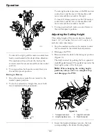
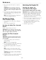
Figure 10
1.
Transport lock knob
3.
Height of cut decal
2.
Height adjustment pin
4.
Deck foot pedal
Transport Lock
Located on RH console in front of the motion
control lever (see Figure 10).
The transport latching mechanism will automatically
engage when the deck is raised to the transport
position. To release the deck from the transport
position: push the foot pedal to remove the load
from the transport latching mechanism, pull up on
the transport lock knob, and let the pedal come back
to lower the deck down to the desired cut height.
Pre-Start
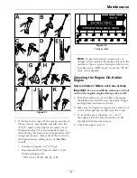
Fill fuel tank on level ground. See
Fuel
Recommendations
in the Specifications section for
additional gasoline information.
26
Содержание RADIUS
Страница 1: ...RADIUS For Serial Nos 400 000 000 Higher Part No 4502 907 Rev B ...
Страница 73: ...Schematics Schematics Electrical Logic Schematic Exmark Engine 73 ...
Страница 74: ...Schematics Electrical Logic Schematic Kohler Engine 74 ...
Страница 75: ...Schematics Electrical Logic Schematic Kawasaki Engine 75 ...
Страница 79: ...Notes 79 ...
Страница 80: ...Notes 80 ...
Страница 81: ...Service Record Date Description of Work Done Service Done By 81 ...
Страница 82: ...82 ...


