Operation
The unit must be tied down and brake engaged when
transporting.
Ignition Switch
Located on right console (see Figure 6).
The ignition switch is used to start and stop the
engine. The switch has three positions “OFF”, “ON”
and “START”. Insert key into switch and rotate
clockwise to the “ON” position. Rotate clockwise to
the next position to engage the starter (key must be
held against spring pressure in this position). Allow
the key to return to the “ON” position immediately
after the engine starts.
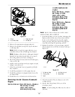
Figure 7
1.
Off
3.
Start
2.
On
Note:
Brake must be engaged, motion control
levers out (neutral lock position) and PTO switch
disengaged to start engine. (It is not necessary for the
operator to be in the seat to start the engine.)
Hour Meter
Located on the control panel (see Figure 6 and
Figure 8).
The hour meter records the number of hours that
the engine has run.
Figure 8
1.
LCD indicators
3.
Hour/Voltage display
2.
Low voltage indicator
light
Fuel Shut-Off Valve
Located by the lower LH ROPS tube mounting.
The fuel shut-off valve is used to shut off the fuel
when the machine will not be used for a few days,
during transport to and from the jobsite, and when
parked inside a building.
Align valve handle with the fuel line to open. Rotate
90° to close.
Drive Wheel Release Valves
WARNING
Hands may become entangled in the rotating
drive components below the engine deck, which
could result in serious injury or death.
Stop engine, remove key, allow all the moving
parts to stop before accessing the drive wheel
release valves.
WARNING
The engine and hydraulic drive units can become
very hot. Touching a hot engine or hydraulic
drive units can cause severe burns.
Allow the engine and hydraulic drive units to
cool completely before accessing the drive wheel
release valves.
Located on the left and right sides underneath the
engine deck.
During normal operating conditions, the drive wheel
release valves are positioned in front of the slots. If
25
Содержание RADIUS
Страница 1: ...RADIUS For Serial Nos 400 000 000 Higher Part No 4502 907 Rev B ...
Страница 73: ...Schematics Schematics Electrical Logic Schematic Exmark Engine 73 ...
Страница 74: ...Schematics Electrical Logic Schematic Kohler Engine 74 ...
Страница 75: ...Schematics Electrical Logic Schematic Kawasaki Engine 75 ...
Страница 79: ...Notes 79 ...
Страница 80: ...Notes 80 ...
Страница 81: ...Service Record Date Description of Work Done Service Done By 81 ...
Страница 82: ...82 ...


