- 26 -
d)
Re-install the blades (if they were removed) by placing a block of wood
between the front or rear baffles and the blade then torquing the blade bolts
to 115-120 ft-lbs. (156-13 N-m). Be sure the spring disc washer cone is
installed toward the bolt head (See Figure 5).
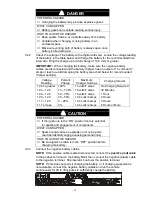
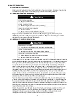
CAUTION
POTENTIAL HAZARD
♦
Operating a mower deck with loose or weakened
blade bolts can be dangerous.
WHAT CAN HAPPEN
♦
A loose or weakened blade bolt could allow a blade
rotating at a high speed to come out from under the
deck, causing serious injury or property damage.
HOW TO AVOID THE HAZARD
♦
Replace the blade bolt after striking a foreign object.
(Use only Exmark replacement parts PN 103-1026 –
blade bolt and PN 103-0865 – spring disk washer).
♦
DO NOT lubricate the threads of the bolt or spindle
before assembly.
♦
Torque the blade bolt to 115-120 ft-lbs. (156-13 N-m).
FIGURE 5
BLADE BOLT INSTALLATION
5.1.7
Check safety interlock system.
Service Interval: Daily
a) Check starting circuit. Starter
should
crank with, parking brake
engaged,
PTO
disengaged
and motion control levers moved out in the
neutral lock
position.
The operator does not need to be in the seat to start the engine.
Try to start with
operator in seat
, parking brake
disengaged,
PTO
disengaged
and motion control levers in the
neutral lock
position - starter
must not crank
.
Try to start with
operator in seat
, parking brake
engaged,
PTO
engaged
and motion control levers in the
neutral lock
position - starter
must not
crank
.
Try to start with
operator in seat
, parking brake
engaged,
PTO
disengaged, and the left motion control lever in,
starter
must not
crank,
repeat again with the
right lever in
, then with
both levers in
-
starter
must not crank.
Содержание Laser Z XP
Страница 50: ... 45 8 ELECTRICAL DIAGRAM 27 HP DAIHATSU DIESEL UNITS ...
Страница 51: ... 46 ELECTRICAL DIAGRAM 31 HP DAIHATSU GAS UNITS ...
Страница 52: ... 47 9 HYDRAULIC DIAGRAM ...
Страница 55: ... 50 ...

