background image

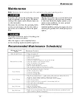
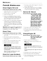
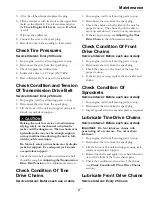
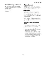
Maintenance

Figure 14

1.

Wheel stop

3.

Indicator hole

2.

Nuts

4.

Indicator notches

4. Lower the wheel stop to reduce the depth. Raise

it to increase the coring depth and as required.

Note:

To ensure that the tines penetrate fully

into the soil, weights can be added to the back
of the machine. The machine has three weight
pockets that hold the weights. When placing
weight, ensure that the load is balanced; if using
only one weight, place it in the center pocket and
if using two, place them in the side pockets.

Note:

The removable weights are heavy. Use

care when lifting them. Make sure that you can
hold them securely before lifting them. Use
caution when positioning your hands so that you
Do Not set them down on your hands or fingers.

5. Tighten the nuts securely to lock the wheel stop

in place.

6. Repeat steps through for the wheel stop

on the left side of the machine. Use the visual
indicator notches in the wheel stop and indicator
holes in the frame to set the wheel stops to the
same height on each side (see Figure 14).

Adjusting the Tine Ground
Engagement Lever

1. Stop engine, wait for all moving parts to stop.

2. Disconnect the wire from the spark plug.

3. Raise the tines to the transport position.

4. The wheel arm and the pivot shaft assembly

should have surface-to-surface contact. If not,
check the distance of the lower lift linkage and
adjust if necessary.

Figure 15

1.

Pivot shaft assembly

3.

Wheel arm assembly

2.

4.8 inches (12 cm)

5. The lower ball joint bolt, on the upper link rod,

should be offset 1/4 inch (6 mm) from the handle
pivot bolt. If not, loosen the lock nuts on the
lift link strap ball joints, adjust as necessary, and
retighten locknuts.

Figure 16

1.

Handle pivot bolt

4.

Lift link strap ball joint

2.

Lower ball joint bolt

5.

Adjust here

3.

1/4 inch (6 mm)

6. Slide the oval locking rings upward on the handle

and fold the handle towards the engine.

27

Содержание ARS180KA21

Страница 1: ...21 INCH WALK BEHIND AERATOR For Serial Nos 314 000 000 Higher Part No 4501 882 Rev A ...

Страница 2: ... allumage par ètincelle de vèhicule est conforme à la norme NMB 002 du Canada The enclosed Engine Owner s Manual is supplied for information regarding The U S Environmental Protection Agency EPA and the California Emission Control Regulation of emission systems maintenance and warranty Keep this engine Owner s Manual with your unit Should this engine Owner s Manual become damaged or illegible repl...

Страница 3: ...ark com for additional safe operation information such as safety tips training materials and Operator s manuals If additional information is needed or should you require trained mechanic service contact your authorized Exmark equipment dealer or distributor All Exmark equipment dealers and distributors are kept informed of the latest methods of servicing and are equipped to provide prompt and effi...

Страница 4: ...tion and Tension Of Transmission Drive Belt 21 Check Condition Of Tine Drive Chains 21 Check Condition Of Front Drive Chains 21 Check Condition Of Sprockets 21 Lubricate Tine Drive Chains 21 Lubricate Front Drive Chains 21 Lubricate Grease Fittings 22 Check Spark Plugs 22 Emptying the Fuel Tank and Cleaning the Fuel Filter 22 Change Hydraulic Transmission Fluid 23 Check Spark Arrester if equipped ...

Страница 5: ...rator controls and safety signs All operators and mechanics should be trained The owner is responsible for training the users Never let children or untrained people operate or service the equipment Local regulations may restrict the age of the operator Only adults and mature teenagers should operate an aerator and even mature teenagers should have adult supervision Be sure a teenager 1 has read an...

Страница 6: ...ns during fueling static electricity can be released causing a spark which can ignite gasoline vapors A fire or explosion from gasoline can burn you and others and cause property damage Always place gasoline containers on the ground away from your vehicle before filling Do Not fill gasoline containers inside a vehicle or on a truck or trailer bed because interior carpets or plastic truck bed liner...

Страница 7: ... or working on the machine After striking a foreign object or abnormal vibration occurs inspect the machine for damage and make repairs before restarting and operating the machine Before clearing blockages Whenever you leave the machine Stop engine wait for all moving parts to stop Before refueling WARNING Hands feet hair clothing or accessories can become entangled in rotating parts Contact with ...

Страница 8: ...airing Keep engine and engine area free from excessive grease or oil and other debris which can accumulate in these areas These materials can become combustible and may result in a fire Let engine cool before storing and do not store near flame or any enclosed area where open pilot lights or heat appliances are present Shut off fuel while storing or transporting Do Not store fuel near flames or dr...

Страница 9: ...r authorized Exmark equipment dealer or distributor or from Exmark Mfg Co Inc Safety signs may be affixed by peeling off the backing to expose the adhesive surface Apply only to a clean dry surface Smooth to remove any air bubbles Familiarize yourself with the following safety signs and instruction labels They are critical to the safe operation of your Exmark commercial aerator 117 2718 119 0217 1...

Страница 10: ...d 3 Raising Lowering the tines push the control lever down to lower the tines pull the control lever up to raise the tines 126 1209 1 Read and understand the operator s manual before servicing this machine 4 Check tire pressure 13 psi 2x every 50 hours 7 Check transmission belt drive tension every 25 hours 2 Grease tine shaft bearings 2x every 25 hours 5 Clean and oil chains 2x every 25 hours 8 Cl...

Страница 11: ...from moving parts keep all guards in place Stop engine and remove spark plug before adjusting servicing or cleaning 2 Warning Disengage tines and stop engine before leaving the operator s position 5 Warning Do Not operate when people and pets are in the area Look behind you when backing up 3 Thrown object hazard Pick up objects before operating 11 ...

Страница 12: ...d under warranty Do Not use gasoline containing methanol Do Not store fuel either in the fuel tank or fuel containers over the winter unless a fuel stabilizer is used Do Not add oil to gasoline Fuel Filter Replaceable In line Fuel Shut Off Valve 1 4 turn increments Operator Controls Self Propel Drive Controls forward and reverse motion of machine Tine Ground Engagement Engages the tines with the g...

Страница 13: ...e in highest position 61 inches 155 cm 42 inches 107 cm Overall Height Operating Stored Handle in lowest position 48 inches 122 cm 31 inches 79 cm Handle in middle position 50 inches 127 cm 33 inches 84 cm Handle in highest position 52 inches 132 cm 34 inches 86 cm Curb Weight Machine only no additional weights 310 lb 141 kg Torque Requirements Bolt Location Torque Engine Mounting Bolts 17 23 ft l...

Страница 14: ...on g013073 1 Figure 3 1 Oval locking ring 2 Slide the oval locking rings down each side of the upper handle over the lower handle locking the handle sections together Product Overview Figure 4 1 Tine ground engagement lever 4 Fuel cap 2 Self propel drive bail 5 Recoil starter 3 Handle 14 ...

Страница 15: ...ezed against the handle the unit ground speed will change based on the distance between the bail and the handle When the bail is released the unit will stop moving Important The tines are rotating when the self propel drive bail is moved out of the neutral position Figure 5 1 Handle 3 Throttle choke lever 2 Self propel drive bail 4 Tine ground engagement lever Tine Ground Engagement Lever Keep han...

Страница 16: ... straps at all times Figure 6 Front Handle Position Lowest Height 1 Trunnion bracket bottom hole 3 Mounting bolt location 2 Lift link straps 4 Handle hardware front holes Figure 7 Middle Handle Position 1 Trunnion bracket bottom hole 3 Mounting bolt location 2 Lift link straps 4 Handle hardware middle holes Figure 8 Rear Handle Position Highest Height 1 Trunnion bracket top hole 3 Mounting bolt lo...

Страница 17: ...g or when the unit is parked inside a building Operating the Self Propel Drive The aerator is variable speed the more you squeeze the drive bail against the handle the faster the machine travels 1 Start the engine 2 Move the self propel drive bail from the neutral position To move forward squeeze the self propel drive bail against the handle see Figure 9 Figure 9 1 Reverse push down and away from ...

Страница 18: ...g Transporting a Unit WARNING Loading the machine onto a trailer without strong enough or properly supported ramps could be dangerous The ramps could collapse causing the unit to fall which could cause injury Use proper ramps that are secured to the truck or trailer Keep feet and legs out from under the unit when loading and unloading If necessary use assistance when loading Use full width ramps w...

Страница 19: ...Interval Maintenance Procedure After the first 5 hours Change the engine oil Before each use or daily Check the engine oil level Check the tines Check for loose hardware Check the condition and tension of the tine drive chains Check the condition of the front drive chains Check the condition of the sprockets Lubricate the tine drive chains Clean the engine and exhaust system area Clean the grass a...

Страница 20: ...injured by contact with the moving tines or by flying debris Always securely install the access panel before operating the machine Check for Loose Hardware Service Interval Before each use or daily 1 Stop engine wait for all moving parts to stop and remove spark plug wire 2 Visually inspect machine for any loose hardware or any other possible problem Tighten hardware or correct the problem before ...

Страница 21: ...nsion in the Adjustments section Check Condition Of Tine Drive Chains Service Interval Before each use or daily 1 Stop engine wait for all moving parts to stop 2 Disconnect the wire from the spark plug 3 Check the chains on both sides of the unit for proper tension The chains should be able to move up and down 1 4 inch 6 mm maximum 4 If chains pop or snap see Adjusting the Tine Drive Chain in the ...

Страница 22: ... spark plug 3 Clean around the spark plug 4 Remove the spark plug from the cylinder head Note Replace a cracked fouled or dirty spark plug Do Not clean the electrodes because grit entering the cylinder can damage the engine 5 Set the gap on the plug to 0 030 inch 0 76 mm Figure 10 Figure 10 1 Side electrode 3 Air gap 0 030 inch 0 76 mm 2 Center electrode insulator 6 Install the spark plug and the ...

Страница 23: ... cable 2 Idler pulley and transmission drive belt 3 Front axle chain sprocket 4 Drive chain 5 Mounting hardware seven locations B Remove the drive belt from the transmission pulley by loosening the nut on the idler pulley C Remove and retain the connecting link from the front axle chain sprocket and remove the chain D Loosen the drive chain idler sprockets on each side of the unit Remove and retai...

Страница 24: ...transmission belt as stated in Adjusting the Transmission Drive Belt Tension in the Adjustments section G Tension the tine drive chains as stated in the Adjusting the Tine Drive Chain in the Adjustments section H Reconnect the self propel drive bail cable 17 Carefully remove the jackstands lower the machine to the ground and remove the overhead hoist hooks 18 Raise and lock the handle into the ope...

Страница 25: ...ough support or may malfunction allowing the unit to fall which could cause injury Do Not rely solely on mechanical or hydraulic jacks for support Use adequate jack stands or equivalent support Adjusting the Self Propel Drive 1 Stop engine wait for all moving parts to stop 2 Disconnect the wire from the spark plug 3 Raise the tines to the transport position 4 Squeeze the self propel bail to the ha...

Страница 26: ...ot flex more than 1 8 inch 3 mm Adjusting the Tine Drive Chain 1 Stop engine wait for all moving parts to stop 2 Disconnect the wire from the spark plug 3 Lift the front of the unit and support using jack stands or equivalent support 4 Check the chains on both sides of the unit for proper tension The chains should be able to move up and down 1 4 inch 6 mm maximum 5 Adjust the idler sprocket 6 Rech...

Страница 27: ...el stop on the left side of the machine Use the visual indicator notches in the wheel stop and indicator holes in the frame to set the wheel stops to the same height on each side see Figure 14 Adjusting the Tine Ground Engagement Lever 1 Stop engine wait for all moving parts to stop 2 Disconnect the wire from the spark plug 3 Raise the tines to the transport position 4 The wheel arm and the pivot ...

Страница 28: ...xhaust system area can cause engine and exhaust area to overheat which can create a fire hazard Clean all debris from engine and exhaust system area 1 Stop engine wait for all moving parts to stop and remove spark plug wire 2 Clean all debris from engine air intake screen around engine shrouding and exhaust system area 3 Wipe up any excessive grease or oil around the engine and exhaust system area...

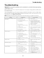
Страница 29: ... spark plug 8 Clean adjust or replace spark plug Engine will not start starts hard or fails to keep running 9 Spark plug wire is not connected 9 Check the spark plug wire connection 1 Engine load is excessive 1 Reduce the ground speed or aeration depth 2 Air cleaner is dirty 2 Clean or replace the air cleaner element 3 Oil level in the crankcase is low 3 Add oil to the crankcase 4 Cooling fins and...

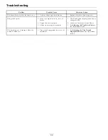
Страница 30: ...and tighten the pump drive belt or change the belt 2 Engine idle not set properly 2 Contact an Authorized Service Dealer Slow ground speed 3 Chains are not properly tensioned 3 See Adjusting the Tine Drive Chain in the Adjustments section The tines drop out of transport when the handle is folded over 1 Tine ground engagement lever is out of adjustment 1 See Adjusting the Tine Ground Engagement Lev...

Страница 31: ...ealership To locate a dealer convenient to you access our website at www exmark com U S or Canada customers may also call 402 223 6375 If for any reason you are dissatisfied with the Service Dealer s analysis or with the assistance provided contact us at Exmark Customer Service Department The Exmark Warranty Company 2101 Ashland Avenue Beatrice NE 68310 402 223 6375 or service exmark com Owner s R...

Страница 32: ...Notes 32 ...

Страница 33: ...Notes 33 ...

Страница 34: ...Service Record Date Description of Work Done Service Done By 34 ...

Страница 35: ...35 ...

Страница 36: ...STOM RIDE SEAT SUSPENSION SYSTEM DUAL TAIL WHEEL FLOOR PAN EXTENDER HITCH KIT LIGHT KIT MICRO MULCH SYSTEM ROLL OVER PROTECTION SYSTEM ROPS SNOW BLADE SNOWBLOWER SUN SHADE TRASH CONTAINER ULTRA VAC COLLECTION SYSTEM ULTRA VAC QUICK DISPOSAL SYSTEM WEATHER CAB Some accessories and options not available for some models Place Model No and Serial No Label Here Included in the Literature Pack or Fill i...

Отзывы: